Define location, pockets, support and separation around the robot
An automated thin-gauge thermoformed tray should be specified around the pick-and-place action, beginning with location and then defining pockets, support and separation. An operator can adjust a hand movement; a programmed machine depends on an established coordinate system. Overall outline acceptance therefore needs to be connected to the actual cavity positions and pickup height.
Start the locating description with the tray seated in the equipment. Identify the edge, hole or face used to establish position and the supports active after clamping. Show suction-cup or gripper access and clearance in the assembly view. Trace how tray location affects the final pickup position across the working area.
Pockets determine the component's orientation and permitted movement. Distinguish the cavity floor protecting a sensitive face, walls locating the component and clearance provided for the handling tool. Observe loading, pickup and empty-tray support separately. A part that sits correctly can still rub during removal or disturb its neighbour when the gripper enters.
Connect flatness and separation to the operating state. Specify whether the equipment uses the tray freely supported, clamped or stacked. Record how vacuum release, lifting and the next tray interact. Sample acceptance should reproduce those actions so that dimensional records and line performance describe the same arrangement.
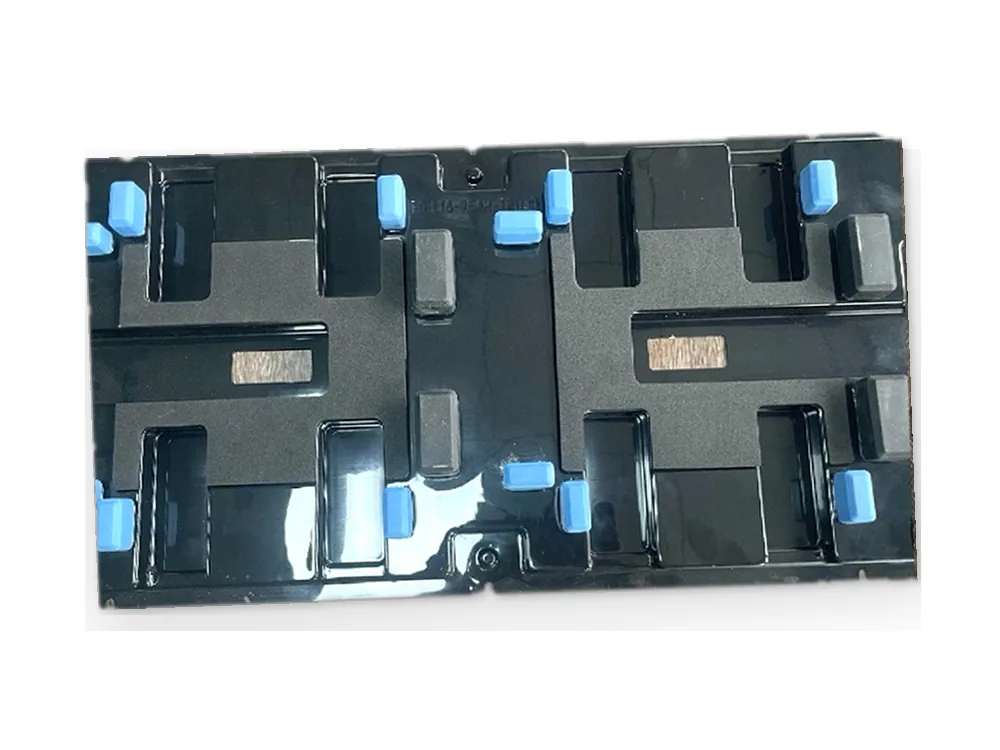
Separate outline, pocket and locating-feature tolerances
方宇(FUNYO) controls thin-gauge trays for automated lines to +0.3 / −0.2 mm. The drawing still needs to identify the controlled features, datums and measurement condition. Pocket width, floor height, outside edges and locating holes serve different functions; place them in one coordinate system before allocating tolerances to the equipment interfaces.
The following FUNYO engineering table covers thin-gauge trays from 2018–2026, in mm, and applies only to thin-gauge trays. Outline tolerance concerns the boundary; pocket tolerance concerns the carried part's cavity. Male- and female-mold tolerances need the relevant tool-contact surface, while the minimum wall between pockets concerns the space separating cavities. Use matching feature definitions when preparing the inspection drawing.
| Thin-gauge tray item (mm) | 2018–2019 | 2020 | 2021 | 2022 | 2023–2024 | 2025–2026 |
|---|---|---|---|---|---|---|
| Maximum depth | 50 | 60 | 70 | 80 | 100 | 120 |
| Outline tolerance | 1.2 | 1 | 0.8 | 0.6 | 0.5 | 0.3 |
| Pocket tolerance | 0.5 | 0.5 | 0.3 | 0.3 | 0.2 | 0.1 |
| Male-mold tolerance | 0.3 | 0.3 | 0.2 | 0.2 | 0.15 | 0.1 |
| Female-mold tolerance | 0.2 | 0.2 | 0.1 | 0.1 | 0.08 | 0.05 |
| Minimum wall between pockets | 5 | 4 | 3 | 2 | 1.5 | 1 |
For thin-gauge trays, outline tolerance changes from 1.2 mm to 0.3 mm, a 75% reduction; pocket tolerance changes from 0.5 mm to 0.1 mm, an 80% reduction, calculated from the table's first and last periods. Use the history to understand the listed range, then review the actual part, pocket arrangement, supports and handling action for the project.
For a multi-pocket tray, dimension working positions from the equipment datum where practical instead of relying entirely on a chain of neighbouring-pocket dimensions. Inspection should reproduce the basis the machine uses. Record differences between corners, long edges and the centre during sample handling to distinguish location, free-state distortion and pocket fit.
Large-Part Thermoforming Tolerances: Drawing Guide explains how to distinguish formed and machined dimensions. Its organization can help a drawing review, while the numerical history above retains its thin-gauge tray scope. Keep the actual support and measurement definitions visible beside the dimensions being accepted.
Give stacked trays a controlled contact and release path
Anti-nesting design aims for a stable stack that releases in the intended sequence. Excessive engagement can combine friction, contact area and trapped air. Examine empty and loaded conditions, showing support points, sidewall clearance, separation direction and the position where the handling tool actually grips the tray.
Identify contacts that limit nesting depth. A path for air to enter during release can reduce suction between nested surfaces; support features should also clear fragile components and the tool's working region. Material surfaces, wear and package loading can alter friction, so test the arrangement through representative handling rather than only lifting an isolated fresh pair.
FUNYO uses an anti-nesting tester to check trays for sticking and a drop tester to simulate handling drops and refine design. A project can describe empty, loaded, stacked and unpacked conditions separately and agree how separation anomalies are recorded. Tie observations and photographs to the approved revision and the handling sequence they represent.
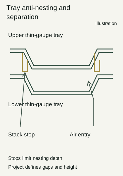
The section illustration explains relationships; the project drawing supplies clearances, stack height and permitted deformation. Run samples with the actual equipment and observe double pickup, tilt, component movement or interruptions. Record the position and direction of an event so the team can identify whether geometry, support or the programmed movement needs adjustment.
Specify ESD function before choosing a material label
An ESD requirement should distinguish low charging, charge dissipation and shielding. Colour and a material description provide identification, while the acceptance decision needs defined performance and conditions. Permanent-type materials generally incorporate the relevant function into the material system; coated types depend on a surface treatment whose condition matters during use.
ANSI/ESD S20.20 sets administrative and technical requirements for establishing, implementing and maintaining an ESD control program.1 ANSI/ESD S541 addresses packaging properties for ESD-sensitive electronic items through production, transport and storage.1 Identify whether the tray works within a protected area or carries components between areas, then assign packaging requirements to that role.
IEC 61340-5-1 also provides requirements for an ESD control program.2 After selecting the contractual standard and edition, specify the tested object, conditions, reporting and traceability responsibilities. Material classification and the operation of an entire protected environment involve different acceptance scopes and should be documented accordingly.
The public ANSI/ESD S541 guidance calls for low-charging, conductive or dissipative packaging inside an EPA.4
The ESD Association's published ANSI/ESD S541 chart classifies conductive resistance as <10⁴ Ω, dissipative as ≥10⁴ and <10¹¹ Ω, and insulative as ≥10¹¹ Ω.3 These are classification boundaries. State the surface-resistance method, conditioning and sample state as well; specify low-charging and shielding functions separately where the handling risk requires them.
FUNYO has promoted permanent-ESD thermoformed boxes since 2014. State the intended classification and operating conditions in the RFQ, then agree testing for the selected material and sample. Include cleaning, repeated handling and storage conditions where relevant so the comparison reflects the intended life of the tray rather than just its incoming label.
Tie measurement and incoming inspection to one revision
An inspection plan should connect dimensions, handling actions and delivered packaging. Dimensional inspection addresses the drawing; anti-nesting testing addresses release behaviour; incoming checks also address identity and condition after transport. Connecting the sample and locating method to the drawing datums helps the supplier and equipment team interpret the same result.
FUNYO has a Nikon VMR-6555 automatic vision measuring system and a VMS-5040 optical measuring system for trays and other small to medium components. List the features requiring measurement, identify free or supported condition and request records that distinguish cavity positions and orientation. Agree the information supplied with the order before approval.
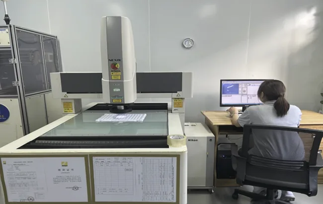
Set sampling around the risk and batch definition. Trial work should examine location, separation and loading; supply inspection follows the approved plan for critical dimensions, appearance, ESD requirements and packing. When a handling anomaly occurs, retain the affected tray and a normal sample from the same batch, together with equipment program and material-state information.
FUNYO has produced thin-gauge trays since 2013. Its thin-gauge production equipment includes 6 automated forming lines with 3 high-speed formers; high-speed vacuum/pressure forming equipment was added in 2022. This provides the thin-gauge production context, while project acceptance follows the drawing, approved sample and agreed inspection records.
During a change, identify whether the locating datum, pocket interface, material or package has moved. A revision affecting the cavity can alter pickup without changing the outline. Retain the approved combination of tray, carried component and machine setting so a later investigation can reproduce the condition that originally passed.
Put machine interfaces and purchasing conditions in one RFQ
A useful RFQ lets the tray supplier understand the handling action as well as the outline. Equipment sketches, locating sections and loaded orientation should share direction references with the tray drawing. The template below gives a sentence of guidance for each field, leaving the response column blank for purchasing, equipment and quality teams.
| Field | Completion guidance | Project response |
|---|---|---|
| Handler type | Identify the robot or handler and provide an action sketch. | |
| Suction cup or gripper | Provide contact geometry, position and approach direction. | |
| Location method | Mark equipment datum edges, holes, faces and supports. | |
| Pocket tolerance | Dimension critical fits against the handler coordinates. | |
| Stack height | State empty and loaded stacking requirements. | |
| Separation method | Describe release direction, air entry and anomaly criteria. | |
| ESD class | State classification, test method and operating conditions. | |
| Cleanliness | Mark contact zones and attach sampling and acceptance requirements. | |
| Reuse cycles | Enter expected reuse and washing arrangements. | |
| Annual volume | Separate planned purchases from replenishment demand. |
Download the automation-tray RFQ checklist and point each open dimension or action to a drawing location. Enter annual demand and reuse separately: the former affects purchasing arrangements, while the latter informs wear, protection and reinspection. An equipment photograph or action sketch can help identify information still needed during the initial inquiry.
Treat the completed form as part of the controlled RFQ package. Give the supplier one drawing revision and ask it to identify assumptions beside the relevant response. Before ordering samples, resolve who provides the carried components and access to representative equipment, and agree how the handling result will be recorded.
When should standardized matrix trays or baking favour injection molding?
Standardized IC matrix interfaces, high-temperature baking or extensive repeated circulation can justify comparing heat-resistant materials and injection-molded trays. Establish the required interface and the baking temperature, time and loaded condition first. Then compare shape, dimensional retention, durability and total supplied scope against those actual requirements.
Where precision location, rigidity or repeated use depends on concentrated small details, injection molding may help integrate them into one component. Thin-gauge forming can still be assessed for part protection, handling clearance and purchasing needs. Use approved samples and representative operation to choose the route rather than relying only on the name of the component.
For baking, include the condition after exposure in acceptance: the component must still locate, separate and protect its contents. The material choice and sample plan should address that use. A supplier's general tray category provides less information than an agreed thermal cycle and an inspection state tied to the intended equipment.
Validate location and separation with loaded samples
Prepare the robot or handler type, cup or gripper drawing, locating method, carried-part information and completed checklist. Check loading, stacking, separation and pickup with samples before approving the dimensional and material-test conditions. Record tray revision, machine program and packaging state so later changes have a common reference.
Review trays and liners, thin-gauge thermoforming and industrial automation applications. For contamination requirements, use Cleanroom Thermoformed Trays: Cleanliness Specs. Keep cleanliness, electrostatic and dimensional clauses distinct, then bring them together in one purchasing revision.