Which dimensions actually need a thermoforming tolerance?
Specify a large thermoformed housing by separating tool-contact dimensions, free-side dimensions and CNC features, then agree on datums and measurement conditions. The purchasing decision is which interfaces need control and how to create and accept them. A single tolerance across the entire drawing hides differences between these features.
Heavy gauge thermoforming draws a heated sheet against a mold, cools it and then removes the formed part for trimming. A single-sided tool directly controls its contact surface. The opposite surface also depends on local wall thickness, which changes as the sheet stretches.
FUNYO(方宇)forms heavy gauge parts up to 2600 × 1600 × 600 mm (102.4 × 63.0 × 23.6 in), with starting sheet up to 15 mm (0.59 in); housing sheet commonly starts at 8–10 mm (0.31–0.39 in). Mark the assembly rim, mounting holes and appearance surface before requesting dimensional commitments. Identify starting sheet and required local finished wall separately so the review can assign suitable inspection points.
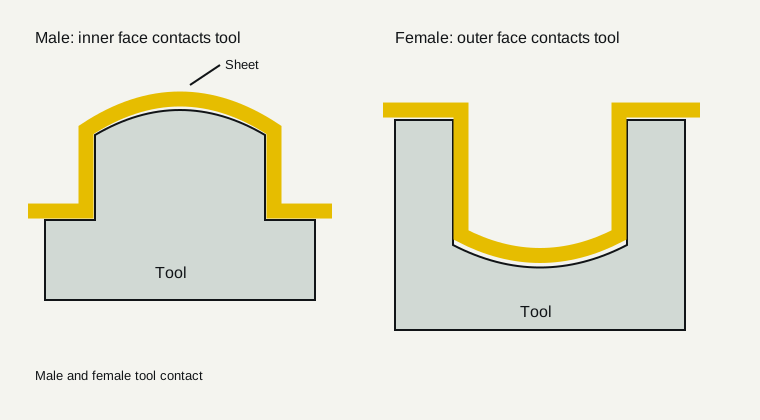
On a male mold, the sheet's inner surface contacts the tool; a female cavity contacts its outer surface. Select the controlled face accordingly. A measurement that spans both faces includes a thickness contribution. A location taken from an untrimmed free surface also has a different meaning from one referenced to a machined edge.
| Dimension class | Main influences | Drawing information to provide |
|---|---|---|
| Tool-contact formed dimension | Tool geometry, cooling shrinkage, release condition | Contact face, datum and measurement conditions |
| Free-side contour or across-wall dimension | Starting-sheet variation, drawing and local wall | Acceptance surface, wall requirement and support |
| CNC hole, slot or trimmed edge | Location, clamping distortion, toolpath and datum transfer | Datum system, critical features and inspection after machining |
How do sheet thickness, shrinkage and temperature affect the reading?
The reading describes a material in a particular measurement state. A sheet stretches differently across a deep wall, a corner and a broad curve. Specifying starting thickness alone leaves the finished thickness distribution unresolved. If a free-side contour determines clearance, identify the region and functional condition that matter rather than relying on the sheet order thickness.
A linear thermal-expansion calculation shows the scale of temperature effects. For this example, assume a coefficient of 90 × 10⁻⁶ /K, a 2 m (78.7 in) measuring length, a 10 K temperature difference and a constant coefficient within that interval. The estimated change is 1.8 mm (0.071 in).
ΔL = α × L × ΔT = 90 × 10⁻⁶ /K × 2000 mm × 10 K = 1.8 mm
For a design calculation, select the coefficient for the actual grade, material direction, temperature interval and restraint. Record the grade, conditioning and measurement environment together when comparing reports from different sites. Use the agreed rest and support conditions for samples and production parts so that contour and mounting-interface results can be compared.
Cooling history, storage and support also affect comparisons. A flexible housing on a bench can take a different shape from the same housing mounted on its fixture. Clamping it flat may change the measured hole relationship. Agree whether inspection represents a free state or a defined support condition, and use that condition for both samples and production acceptance.
What does FUNYO's thin-gauge tray history establish?
The following capability history applies only to thin-gauge thermoformed trays, with all dimensions in mm. Record the product type, period, measured feature and datum together during review, then select the inspection characteristics that correspond to the order.
| Thin-gauge tray capability (mm) | 2018–2019 | 2020 | 2021 | 2022 | 2023–2024 | 2025–2026 |
|---|---|---|---|---|---|---|
| Maximum depth | 50 | 60 | 70 | 80 | 100 | 120 |
| Outline tolerance | 1.2 | 1 | 0.8 | 0.6 | 0.5 | 0.3 |
| Groove tolerance | 0.5 | 0.5 | 0.3 | 0.3 | 0.2 | 0.1 |
| Male-tool tolerance | 0.3 | 0.3 | 0.2 | 0.2 | 0.15 | 0.1 |
| Female-tool tolerance | 0.2 | 0.2 | 0.1 | 0.1 | 0.08 | 0.05 |
| Minimum width between grooves | 5 | 4 | 3 | 2 | 1.5 | 1 |
For thin-gauge trays in 2025–2026, outline tolerance is 0.3 mm (0.012 in) and groove tolerance is 0.1 mm (0.004 in). Thin-gauge trays for automated lines use +0.3 / −0.2 mm (+0.012 / −0.008 in). Identify outline, groove and automated-location requirements separately in the order review and connect each to its inspection record.
Investigate thin-gauge tray variation by checking sheet consistency, heating distribution, cooling, tool geometry and cutting location separately. Compare the same feature after forming, cooling and cutting to distinguish shape changes from finishing-location effects. That sequence helps the team choose a focused trial and retain a measurement record against the feature being investigated.
For thin-gauge trays, review the formed-feature dimension chain separately from the cutting and location chain for the overall outline. Check whether the latter adds locating variation. The smaller male- and female-tool entries are a reason to distinguish inspection characteristics; confirm their datums and measured faces for the actual tray.
Which published accuracy figures can inform an RFQ?
Read published accuracy figures together with their material, process and fixture conditions. A small-part routing figure can prompt questions about location, while a specialist sheet example can help frame a forming-route review. Turn those conditions into RFQ questions and request answers against the large housing’s geometry, support and measurement state.
A sheet manufacturer's thermoforming manual gives five-axis robotic trimming accuracy of 0.010–0.015 in (0.254–0.381 mm) for reasonably small parts in a rigid, accurate fixture.1 Specify fixture contact points, locating datums and the inspection method with the trimming proposal.
A sheet manufacturer's technical page for a particular custom translucent sheet configuration compares vacuum forming ±0.010 in with drape forming ±0.030 in: ±0.254 mm and ±0.762 mm respectively.2 Use the example to discuss forming routes, then request a measurement plan for the actual material, tool-contact face and geometry.
| Published figure and condition | Question it helps ask | Conditions to review |
|---|---|---|
| Small-part five-axis routing accuracy 0.254–0.381 mm (0.010–0.015 in), rigid accurate fixture | How will the trim be located, supported and verified? | Trim datum and fixture location |
| Specific sheet example [2]: vacuum ±0.254 mm (±0.010 in), drape ±0.762 mm (±0.030 in) | Which forming route and tool-contact face are being assessed? | Actual sheet and forming route |
| ISO 2768-1 scope includes metal removal and sheet-metal forming | Which finishing features can use an agreed general tolerance? | Agree on scope and class feature by feature |
ISO 2768-1's public scope describes workpieces produced by metal removal or formed from sheet metal. If a drawing invokes the standard, identify the applicable features and class, and address the plastic formed contour separately. A standard number alone leaves datums, measurement state and critical assembly interfaces unresolved.3
The practical RFQ question is therefore specific: which dimension is measured, from which datum, in what supported state, using which acceptance method? Ask suppliers to answer that question against the drawing. Comparing the smallest numbers on unrelated technical pages would discard the conditions that made those numbers meaningful.
Which interfaces deserve CNC finishing and separate inspection?
Review mounting holes, mating slots and trimmed datum edges as critical features before choosing the machining and inspection plan. FUNYO uses three- and five-axis CNC for tooling, trimming and deburring, holes and slots. The drawing, location method and sample acceptance still determine the requirements for a particular feature.
CNC changes how a selected feature is generated. A toolpath can control a hole relative to the machining coordinate system, but that system depends on how the housing is located. If a fixture bends the part differently on each loading, release can change the finished relationship. Locating from a variable free surface transfers that forming variation into the machined feature.
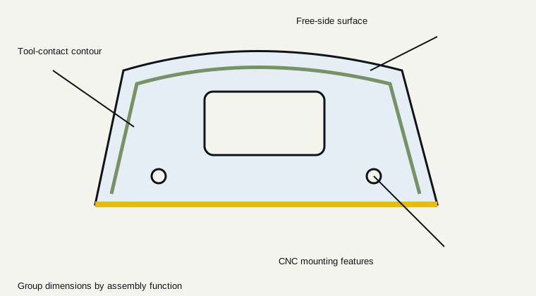
Begin with functional assembly datums, then review the fixture's contact points, clamping direction and inspection support. A display opening can have several independent requirements: opening size, position relative to mounting holes, and the visible gap after assembly. Identify which relationship drives acceptance rather than applying the same tight limit to every surrounding surface.
FUNYO's inspection equipment includes a Nikon VMR-6555 automatic video measuring system and a VMS-5040 optical 2.5D video measuring system for trays and small to medium parts. Agree on the overall measurement method for a large housing during the project review. Identify the methods and records for the overall contour, local holes and assembly relationships in the RFQ.
How should gauges and measurement equipment work together?
Select inspection tools for the feature and acceptance state. Calipers can address accessible local dimensions. A dedicated gauge can check an assembly relationship if its contact points and pass criteria are defined. Optical measurement suits visible edges and holes; contact coordinate measurement requires review of probe contact, support and coverage. Put the selected methods, sampling scope and report requirements in the inspection plan.
Record post-forming conditioning and rest conditions, the scope of sampling or complete inspection, and the results retained in the report. A flexible contour and a local hole pattern may use different measurement methods, but their datums should correspond. That prevents separate reports from passing while leaving the assembly relationship unresolved.
When should you choose another process or change the structure?
Reconsider the structure when assembly depends on a free-side contour while tightly constraining both surfaces and several rigid interfaces. Injection molding, a separately machined interface or a split assembly may deserve review. Asking the formed shell to provide every precision fit can move effort into complex fixtures and individual adjustment.
Small thin-walled parts with dense snap fits, bosses and details on both faces also justify an injection-molding assessment. Where the function depends on metal load paths or metal joining, include sheet metal or metal machining in the process review. Start with the service requirement rather than forcing the design to match a generic tolerance table.
Two questions keep the decision concrete. Can the critical relationship be controlled independently through clear datums and selected finishing? Can inspection reproduce the agreed assembly state? If either remains unresolved, review the structure and measurement plan before approving production tooling. That exposes the uncertainty during sample evaluation instead of after procurement.
What should go into the drawing review before quotation?
Send a drawing review sheet that combines critical interfaces, dimension classes and measurement conditions. Let suppliers respond against each line. Write the function and acceptance method before settling the numerical limit; reserve general tolerances for noncritical dimensions within a stated scope.
| Review item | Specify on drawing or inspection agreement | Review response |
|---|---|---|
| Drawing revision | Use the same revision for quotation, samples and inspection | |
| Critical function | Identify assembly interfaces and acceptance criteria | |
| Dimension class | Separate tool-contact, free-side and CNC features | |
| Datum system | Define functional datums and location order | |
| Tool-contact face | Select the controlled inner or outer surface | |
| Thickness definition | Separate starting sheet from local finished wall | |
| Measurement temperature | Agree on conditioning and measurement environment | |
| Measurement support | Define free state or supported and clamped state | |
| Finishing scope | Identify holes, slots, trim and their datums | |
| General tolerances | Specify standard, class and applicable features | |
| Inspection method | Agree on instruments, locations and records | |
| Samples and revisions | Record deviation handling, revision and approval |
The table is identical to the downloadable CSV. Retain the agreed responses in the controlled drawing or inspection agreement, with revision and approval responsibility. During sample review, repeat measurements using the agreed datums, support and temperature conditions. Classify deviations as formed-contour, free-surface or finishing issues before changing the process.
This review also makes quotations comparable. A supplier pricing a supported assembly check is carrying a different scope from one pricing only a free-state edge measurement. Resolve the difference in the RFQ, and keep the sample report tied to the approved revision. The resulting tolerance is a project acceptance requirement rather than a number borrowed from another product.
Download the large-part tolerance drawing checklist. Review heavy gauge thermoforming capacity, CNC machining and trimming and dimensional inspection equipment. For the budget decision, use the thermoforming versus injection molding break-even calculation.
Review draft, radii and stretching zones with the heavy-gauge thermoforming design guide.