Choose the tool-contact surface before choosing the mold
Heavy-gauge thermoforming design starts by deciding which surface contacts the tool, then allocating draft, radii and machined features. An appearance surface, an assembly datum and a thin corner may be on different sides of the same cover. Mark each requirement separately.
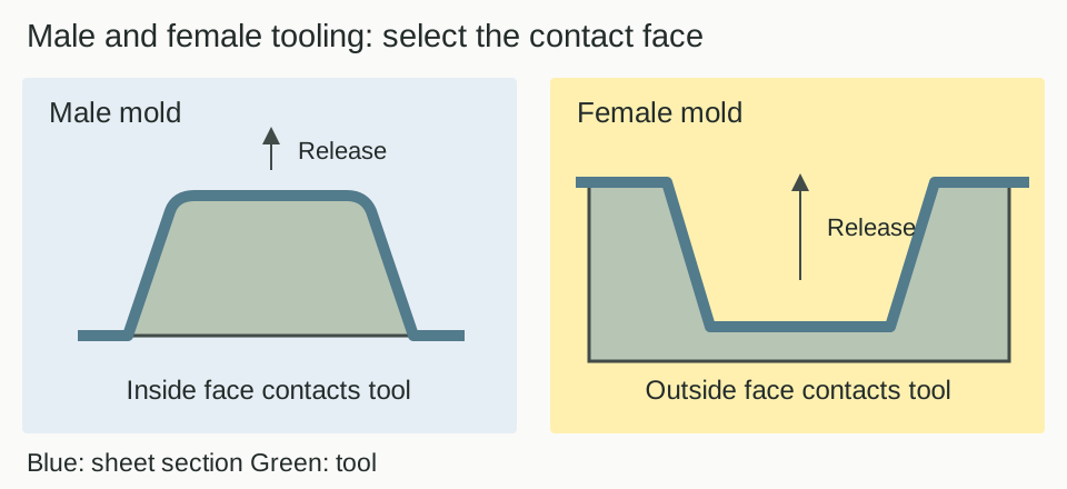
A male tool presents a raised shape and controls the inside surface of a shell. A female tool receives the sheet into a cavity and controls the outside. The contacting face follows the tool directly; the opposite face also reflects starting gauge and local stretching. Check a sheet's original texture separately from a texture reproduced from the tool.
Show the surrounding frame in the section drawing. Locate critical holes and trimmed edges from assembly datums rather than allowing every fit to follow an uncontrolled surface. The large-part tolerance guide explains the distinction between formed, free-side and machined dimensions.
Check draft against release direction, material and texture
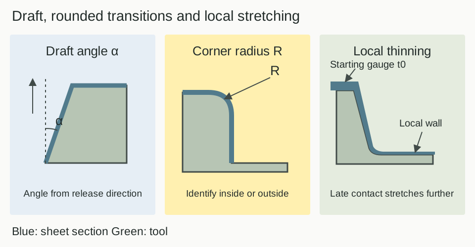
Draft is the inclination of a wall relative to its release direction. Draw that direction before selecting an angle. A cooling sheet can grip a male tool, while shrinkage inside a female cavity can help the part move away from the wall. Check raised and recessed areas separately, including the path required to lift the whole shell away.
FUNYO heavy-gauge housing draft starting points are male ≥3°, or ≥5° above 200 mm wall height, and female ≥1°. For tool-contact texture, add 1° per 0.025 mm depth; sheet texture facing away adds no extra draft. Confirm these starting points with the first article.
A sheet manufacturer's guide gives minimum draft references of 2–3° for male molds and 0.5–1° for female molds.1 The same guide suggests about 1° extra draft per 25 μm of texture depth.1
Changing draft also moves the opening perimeter and affects the space around mating parts. Include the frame, visible seam and mounting supports in that check. If restricted release needs additional tooling or a different removal sequence, keep those operations beside the proposed mold design and quotation scope.
Ten FUNYO starting points for heavy-gauge housings
These are drawing-review defaults; confirm the final geometry with the first article.
| Item | FUNYO starting point | Published comparison |
|---|---|---|
| Draft | Male ≥3°; ≥5° above 200 mm wall height; female ≥1° | Male 2–3°, female 0.5–1°; source [1] |
| Texture | Tool-contact texture: add 1° per 0.025 mm depth; no extra angle for sheet texture facing away | About 1° per 25 μm; source [1] |
| Radius | ≥starting gauge, preferably ≥2×; about 16 mm for 8 mm sheet | Deep-drawn female-mold parts: ≥12.7 mm or 45° miter above 2:1; about 25.4 mm at 3:1; source [2] |
| Areal draw | Typical housings ≤3:1; revise or split above this | Preferably below 3:1; source [2] |
| Female depth | Depth ≤opening width (≤1:1); consider splitting deeper parts | Female depth ratio 2:1; source [3] |
| Process edge | About 30–50 mm outside each trim edge for clamping and location | — |
| Hole edge | ≥2× starting gauge from trim line and start of radius | — |
| Thinnest wall | Estimate deep corners at about 1/3 of starting gauge | — |
| Ribs | Height ≤base width; base ≥3× gauge; root radius ≥gauge | — |
| Shrinkage | ABS 0.5–0.7%; PC 0.6–0.9%; PVC 0.4–0.6%; PETG 0.3–0.6%; PP 1.5–2.0%; correct after first article | — |
Use radii and area draw ratio to find thinning risks
FUNYO heavy-gauge housing radius starting points are ≥starting gauge, preferably ≥2× gauge: about 16 mm for 8 mm sheet, confirmed with the first article.
Radii connect material distribution, strength and available space. For deep-drawn female-mold parts, a sheet manufacturer's thermoforming manual suggests at least 12.7 mm (1/2 in) corner radius or a 45° miter above 2:1 areal draw, and about 25.4 mm (1 in) at 3:1.2 State whether the drawing radius lies on the inside or outside face and which thickness definition it uses.
FUNYO heavy-gauge housing starting points are areal draw ≤3:1 and female depth-to-opening width ≤1:1; revise or split deeper shapes, then confirm with the first article.
Depth-to-width ratio describes shape; areal draw ratio describes how much formed surface the available sheet must cover. A sheet manufacturer's technical brief recommends a female-mold depth ratio no greater than 2:1 and defines area ratio as original sheet area divided by formed area; this article uses the reciprocal for areal draw ratio.3 Use consistent CAD boundaries, including participating flanges and separating material retained in clamping scrap.
Areal draw ratio DR = formed surface area Af ÷ original sheet area A0.
Average wall thickness ≈ starting sheet thickness t0 ÷ DR.
The manual defines draw ratio by area and recommends keeping it below 3:1 where possible.2 Plug assist can substantially increase the usable female-mold depth ratio above the 2:1 reference.3 A narrow pocket can stretch severely even when the whole-part area ratio looks modest. Identify early-contact areas, deep corners and local sheet supply alongside the global calculation.
Example: calculate a drafted rectangular box
This geometry example uses a 400 × 300 mm opening (15.7 × 11.8 in), 100 mm depth (3.9 in), 5° draft and 8 mm starting sheet (0.31 in). Ignore corner radii, flanges and clamping edges, and calculate at a thin-wall midsurface. Assume material is redistributed within the opening boundary. These are calculation inputs; check the actual formed sample for acceptance. Carry unrounded values through the calculation; the displayed intermediate values use three decimal places.
- Effective original area A0: 400 × 300 = 120000 mm².
- Inward offset on each side: 100 × tan(5°) = 8.749 mm. Bottom dimensions are 382.502 × 282.502 mm (15.1 × 11.1 in).
- Wall slant height s: 100 ÷ cos(5°) = 100.382 mm (4.0 in).
- Bottom area: 382.502 × 282.502 ≈ 108057.758 mm².
- Four-wall area: s × (400 + 382.502 + 300 + 282.502) ≈ 137021.863 mm².
- Formed area Af: bottom plus walls ≈ 245079.621 mm².
- Areal draw ratio: 245079.621 ÷ 120000 ≈ 2.04233.
- Average wall: 8 ÷ 2.04233 ≈ 3.92 mm (0.15 in).
The 3.92 mm average (0.15 in) leaves local distribution unresolved: corners, late-contact regions and areas furthest from the tool can be thinner. Mark sample thickness checks at those locations and around loaded attachments. Compare a larger transition radius, shallower geometry or different split before simply increasing the starting gauge. Update the CAD area when the geometry changes.
Specify starting gauge separately from the finished wall
FUNYO heavy-gauge housing thinnest-wall starting point is about 1/3 of initial gauge at deep corners; confirm through first-article thickness measurement.
The purchase sheet and the finished shell need separate thickness requirements. 方宇(FUNYO) commonly uses 8–10 mm starting sheet for housings (0.31–0.39 in), with sheet up to 15 mm (0.59 in). Use these limits when selecting sheet and evaluating feasibility, then identify the finished-wall requirements around the actual part's mounting, loading and deep-draw regions.
Create a thickness map tied to drawing zones. State whether measurement takes place on a supported loose cover or in its assembly condition. Use the same zone identifiers in sample approval, inspection and engineering changes so a thin region leads to a specific geometry decision rather than a general request for thicker material.
More starting material also changes heating and handling conditions. Where the weakness is local, check the transition, material supply and split arrangement first. Keep acceptance tied to the finished region while comparing feasible sheet options. The thermoforming materials guide supports that discussion without replacing the grade check.
Check the removal path before adding undercuts or mounts
For an undercut, first draw how the tool moves away and how the shell is removed. Industry approaches include movable tool sections, removable pieces, separate components and features completed after forming. Compare the access and service implications of each arrangement. FUNYO heavy-gauge undercuts, bosses and inserts are confirmed by project, using a section drawing and a defined connection proposal.
FUNYO heavy-gauge housing rib starting points are height ≤base width, base width ≥3× starting gauge and root radius ≥gauge; confirm with the first article.
Broad, gradual formed ribs can add geometric stiffness, but their roots, crowns and adjacent channels also need analysis of material distribution. A deep narrow internal feature concentrates stretching. Compare a separate bracket or frame where it can carry the attachment loads while the appearance shell establishes the visible contour and access boundary.
For attached bosses, brackets or inserts, identify the load path, installation access and service-removal sequence. If the proposal uses adhesive or fasteners, include material compatibility and sample validation with the relevant parties. Ask the quotation to identify who supplies and installs each item, keeping component geometry and assembly responsibility together.
Design holes, slots and trim with the locating fixture
Screen openings, mounting holes, slots and mating edges can be CNC-machined after forming when cutters and supports can reach them. FUNYO uses 3-axis and 5-axis CNC for tooling, trimming, deburring, holes and slots. Supply the formed blank, final contour and locating surfaces as distinguishable drawing information.
FUNYO heavy-gauge housing process-edge starting point is 30–50 mm per side; keep hole edges ≥2× gauge from the trim line and radius start, confirming with the first article. Shrinkage starting points are ABS 0.5–0.7%, PC 0.6–0.9%, PVC 0.4–0.6%, PETG 0.3–0.6% and PP 1.5–2.0%, corrected after the first article.
Use the process edge for clamping, support and cutter entry, keeping the scrap stable. Put the excess edge on the blank drawing and the final edge on the machining drawing. When a mounting hole refers to an assembly datum, the fixture should reproduce that relationship so inspection can explain the hole and trimmed profile together.
Check the connecting material left around an opening, its inside corners and the visible cut edge. Cable passages involve contact with an edge; screen surrounds involve fit and appearance gaps; access panels involve repeated removal and support. Those functional requirements make the machining and inspection scope clearer than an equipment name alone.
Close the drawing check with a 20-item checklist
The checklist records whether the drawing states these conditions; use the blank response column for Yes, No or Not applicable. Keep the reference and its source beside the question, then identify the drawing view that resolves it. A material, finish or tool change can reopen a previously answered item, so retain the completed checklist with its controlled drawing revision.
| Item | Check question | Reference and source | Yes / No / N/A |
|---|---|---|---|
| Tool-contact face | Identify appearance, assembly and contacting faces | Check with appearance and assembly drawings | |
| Male draft | Show direction, wall height and release path | FUNYO starting point ≥3°, ≥5° above 200 mm; source [1] 2–3° | |
| Female draft | Check cavity regions and removal separately | FUNYO starting point ≥1°; source [1] 0.5–1° | |
| Textured face | Identify texture origin and direction | FUNYO tool-contact starting point: add 1° per 0.025 mm; sheet texture facing away adds none; source [1] about 1° per 25 μm | |
| Release path | Show tool motion and removal order | Check sections and tooling proposal | |
| Radius | Identify inside/outside radius and gauge definition | FUNYO starting point ≥gauge, preferably ≥2×; deep-drawn female-mold parts: source [2] ≥12.7 mm or 45° miter above 2:1, about 25.4 mm at 3:1 | |
| Depth ratio | Record depth and opening width | FUNYO female starting point ≤1:1; source [3] female 2:1 | |
| Area boundary | Include flanges participating in forming | Set area boundaries from drawing and sample | |
| Draw-ratio limit | Check material and forming method | FUNYO areal starting point ≤3:1; source [2] preferably below 3:1 | |
| Starting gauge | Separate sheet purchase from finished wall | FUNYO housing starting sheet commonly 8–10 mm (0.31–0.39 in) | |
| Gauge envelope | Check required starting sheet | FUNYO sheet up to 15 mm (0.59 in) | |
| Finished wall | Mark critical zones and measurement state | Check zones and sample thickness checks | |
| Local thinning | Identify deep corners and late contact | FUNYO deep-corner starting point about 1/3 of starting gauge; first-article measurement | |
| Undercuts | Show moving sections and removal path | Heavy-gauge proposal confirmed by project | |
| Ribs | Check roots, crowns and nearby channels | FUNYO starting point: height ≤base; base ≥3× gauge; root R ≥gauge | |
| Bosses and inserts | Define connection and supplied scope | Heavy-gauge proposal confirmed by project | |
| CNC features | Mark holes, slots, final edges and datums | FUNYO 3-axis and 5-axis CNC scope | |
| Trim allowance | Check clamps, location and cutter entry | FUNYO process-edge starting point: 30–50 mm outside each trim line | |
| Hole-edge distance | Dimension from hole edge to trim line and radius start | FUNYO starting point ≥2× starting gauge | |
| Measurement datums | Connect frame and inspection support; link drawing and approved-sample revision | Agree assembly drawing and measurement state |
The download matches the webpage. Source numbers correspond to the source list at the bottom of the article. Attach the relevant sections, mating-part information and the decisions still required from the supplier. Purchasing can then compare tooling, fixtures and finishing against the same supplied state, while engineering can trace a proposed change to its effect on the assembly.
When should you choose another process or split the structure?
Dense internal bosses, intricate snap features, small deep channels or precise contours on both faces justify comparing another route early. Separating the broad appearance surface from the load-carrying structure can also reduce the demands placed on a single formed shell. Select the functional architecture before comparing tooling and production proposals.
Where an assembly tolerates little cumulative movement, concentrate the controlled relationships on suitable locating and machined surfaces. An independently machined bracket can provide precision location; a mature geometry with concentrated internal detail may merit injection molding. Keep a common assembly datum so that samples from different routes face the same acceptance decision.
Send the appearance face, thinning zones and datums for review
Send the drawing revision, release direction, required finished-wall zones, frame information and completed checklist. FUNYO's maximum heavy-gauge part is 2600 × 1600 × 600 mm (102.4 × 63.0 × 23.6 in). Check that envelope together with splitting, starting gauge and machining access rather than treating overall size as the complete feasibility decision.
FUNYO started heavy-gauge work in 2023 and established its dedicated division with heavy-gauge and 5-axis equipment in 2025. It responds within 4 hours and provides a suitability assessment and comparison quotation within 2 working days. Define removal, sample thickness measurements and approval criteria during the project review.
Check the heavy-gauge capability and tooling and process engineering, then bring the drawing and checklist to the project inquiry.