Which part of the charger enclosure are you actually buying?
Choose the manufacturing route for a defined enclosure component, with the protective structure and the appearance cover assessed separately. A large curved cover whose shape is still evolving can justify a heavy-gauge thermoforming review. A metal frame, a molded interface and an appearance shell may each use a different process while sharing the same assembly and acceptance plan.
The frame carries the equipment and establishes mounting relationships. The appearance cover provides the visible form and access surfaces. A front panel brings together user interfaces; a screen surround locates the display opening; the connector holster has its own attachment and handling requirements. Mark those boundaries before asking a supplier to quote an unspecified complete enclosure.
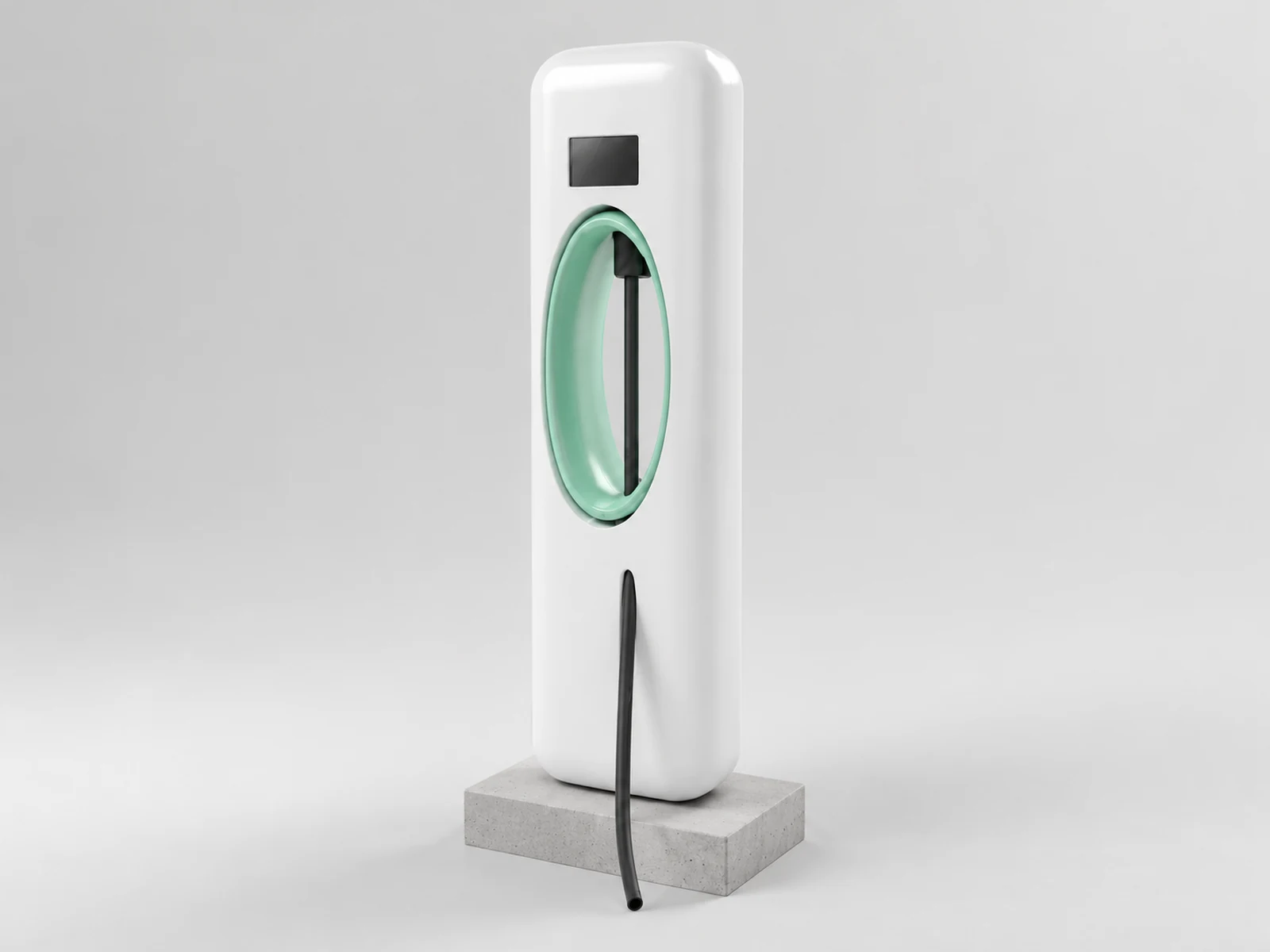
Agree which party designs the frame, defines the sealing interfaces and supplies the display and holster hardware. The cover drawing should reference those interfaces without taking over every structural function. This makes process selection a component decision, rather than treating a single manufacturing method as responsible for all of the equipment's performance.
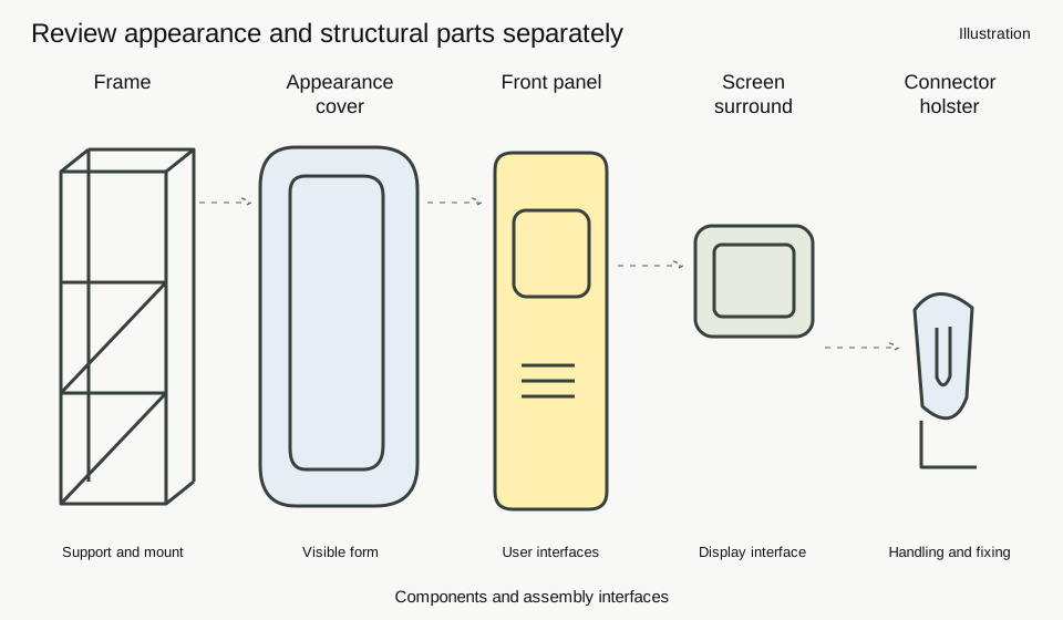
Keep the exploded arrangement connected to a part list. For each component, identify the supplied state, the assembly datum and the acceptance record. That gives purchasing a way to compare complete scopes even when the proposals split the enclosure differently. A component that moves from the shell to the frame should remain visible in the cost and assembly comparison.
How do thermoforming, injection molding and sheet metal compare?
Compare tooling investment, component geometry and recurring finishing work against the same delivered scope. Thermoforming shapes sheet and finishes selected edges and openings afterward. Injection molding puts more features into the cavity. Sheet-metal fabrication builds form through cutting, bending and joining. The useful question is how each route creates and locates the interfaces that the charger needs.
方宇(FUNYO)uses three- and five-axis CNC for tooling, trimming, deburring, holes and slots. A curved shell can therefore be reviewed as a formed cover with selected machined interfaces. Ask which features come from the forming surface, which are generated during machining and which remain functions of the frame or purchased hardware.
The company figures in the thermoforming column describe the heavy-gauge forming envelope and tooling only. Compare the tooling-cost ratio at the same part scope, and keep tool construction separate from the complete delivery schedule. The other columns describe process decisions qualitatively, rather than assigning another route the same supplier figures.
| Comparison | Heavy-gauge thermoforming | Injection molding | Sheet metal |
|---|---|---|---|
| Tooling period | About 1–3 weeks; review cover geometry | Assess cavity, structure and trial schedule | Assess cutting, bending, fixtures and joining |
| Tooling expense | Heavy-gauge tooling below 1/10 of comparable injection tooling; tooling only | Quote the feature and cavity scope | Quote forming tools, fixtures and operations |
| Size envelope | Up to 2600 × 1600 × 600 mm (102.4 × 63.0 × 23.6 in) | Review molding equipment, parting and structure | Review stock, bends, split parts and seams |
| Curves and features | Sheet follows the tool; openings can be finished afterward | Integrate shape and detail in the cavity | Create form through cutting, bending and joining |
| Revision work | Review tool surface, fixture and openings separately | Review cavity changes and associated structure | Review flat pattern, bends and connections |
| Purchase-volume decision | Compare investment with releases and revision plans | Assess amortization against stable lifetime demand | Assess batches and the fabrication sequence |
A changed appearance surface may require different work from a moved screen opening. Ask for the revised tool, fixture and finishing scope separately. Compare lifetime delivered cost and revision assumptions using the thermoforming versus injection-molding break-even method, then choose which proposals deserve samples and detailed quotations.
Use a process matrix before asking for prices
Read each row as a condition to review, rather than adding the labels into a score. The size row concerns the form of the cover; the volume row concerns purchasing and investment; the shielding row concerns the electrical function. A route can suit the visible shell while another route supplies the protective structure.
| Selection condition | Thermoforming | Injection molding | Sheet metal |
|---|---|---|---|
| Size and form | Suitable: medium-to-large curved appearance covers | Assess: equipment and parting arrangement | Suitable: bent panels or split structures |
| Annual demand and buying | Suitable: releases with tooling-investment sensitivity | Assess: amortize tooling against stable demand | Suitable: organize operations around panel batches |
| Revision frequency | Suitable: review curves and finished openings separately | Assess: cavity changes affect investment | Suitable: review flat-pattern and hole changes |
| Outdoor use | Assess: weathering material and sealing interfaces | Assess: grade, joints and thermal conditions | Assess: corrosion, finish and connections |
| Shielding requirement | Unsuitable: an insulating appearance cover alone provides no metal shield | Unsuitable: untreated plastic alone provides no conductive shield | Suitable: review metal continuity and bonding |
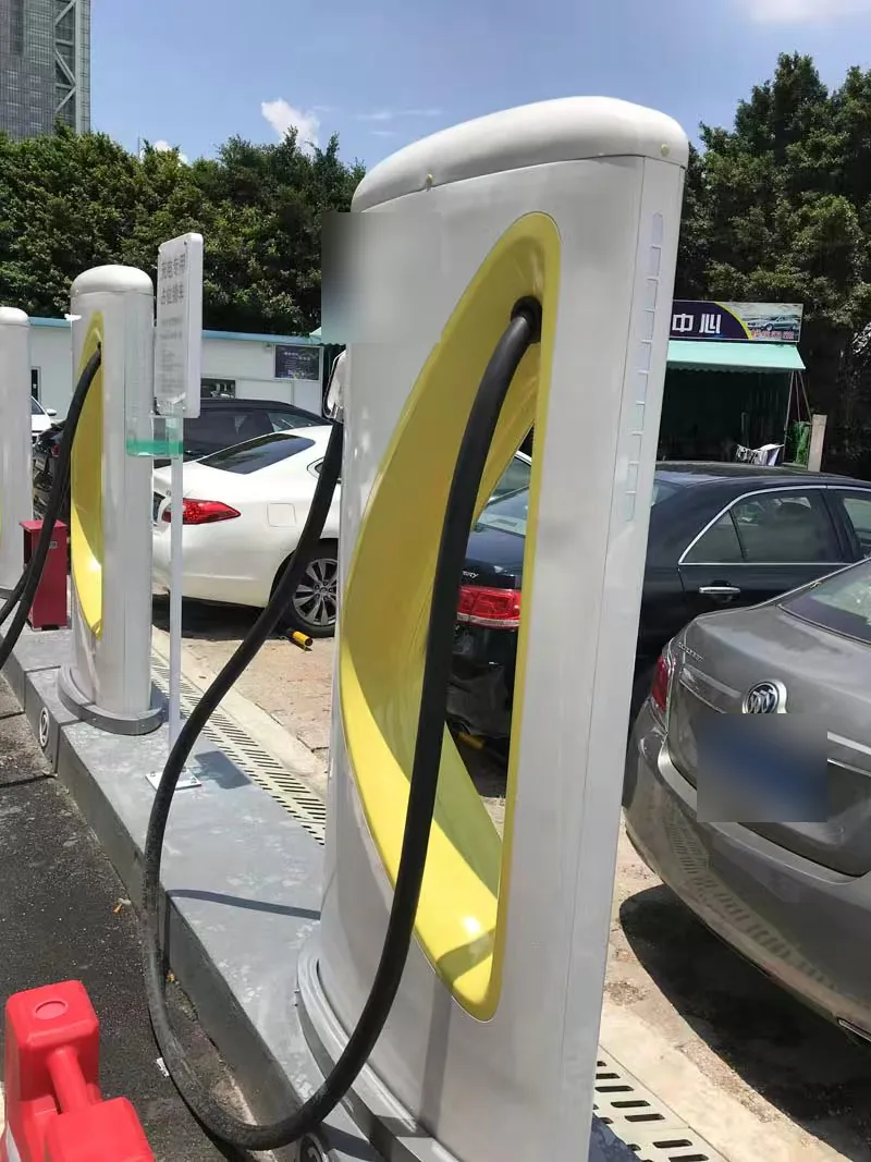
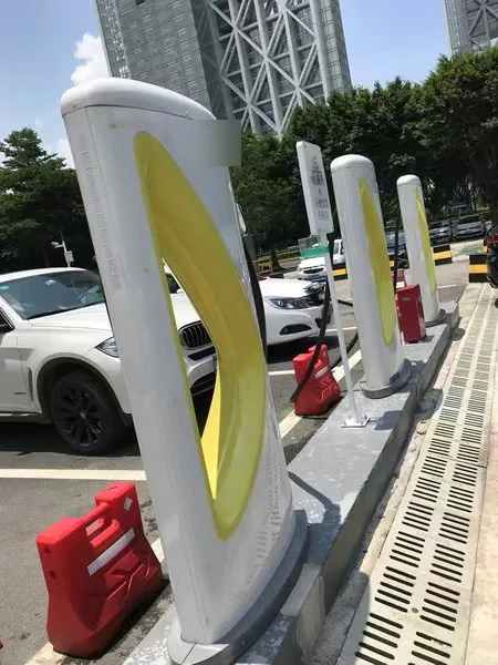
The following reference photographs show the form of comparable products; they are not FUNYO delivery cases. Keep the illustrated design concept and these reference shapes separate from the controlled assembly drawing used for quotation.
What do IP, IK and material flammability actually assess?
Specify the target assessment and who will test it before treating a material or forming route as the answer. IP under IEC 60529 classifies protection provided by enclosures. IK under IEC 62262 concerns external mechanical impacts. UL 94 concerns flammability tests for polymeric materials used in equipment parts. The material, the assembled enclosure and the charging system belong to related but distinct evaluations.123
For ingress protection, the agreed test configuration needs to represent the joints, access panels, display opening, cable entries and ventilation arrangement. Material stiffness and the shape of a sealing land affect how the assembly holds its interface. The equipment designer sets the target configuration and agrees the verification plan with the responsible test laboratory or assessment body.
Impact performance also involves the assembled support arrangement. The wall, curvature, fastening points and distance from the frame affect how a cover takes a load. Identify the locations needing evaluation and the condition of the equipment during the test. Ask the laboratory to confirm the applicable scope and report the tested configuration; keep that configuration linked to the approved drawing.
UL 94 covers flammability tests for polymeric materials used in devices and appliances.3 Material selection should therefore identify the evidence for the chosen grade and the relevant thickness, while the equipment assessment addresses its use in the final assembly. Agree who obtains the material documentation and who commissions the equipment evaluation, so a purchasing file connects the evidence to the supplied part.
IEC 62262 applies to equipment enclosures where the specific standard establishes enclosure protection against mechanical impacts.2 IEC 61851-1:2017 applies to EV supply equipment for charging electric road vehicles.4 Connect the enclosure evidence with the controlled equipment drawings, assembled condition and adopted standards, and identify the party responsible for each assessment.
Which outdoor conditions should go into the material request?
Write outdoor exposure as a purchasing condition with an agreed evaluation method. Identify sunlight exposure, color expectations, service temperature, local heat sources, cleaning chemicals and the condition of sheltered and exposed surfaces. These inputs help the material supplier and equipment engineer decide which evidence and samples are relevant to the proposed enclosure.
FUNYO evaluates ABS, PC, PVC, PETG and PP sheet for heavy-gauge work. Starting sheet can be up to 15 mm (0.59 in), with housings commonly using 8–10 mm (0.31–0.39 in). Starting thickness belongs beside the required finished wall in the material review, because drawing a broad curve or a deep feature redistributes the sheet.
Weathering and flame-retardant grades are confirmed by project. Include UV stabilization, the color reference, color-change acceptance and the thermal conditions to be evaluated in the material request. Ask for documentation tied to the actual grade and supply condition, then decide how the formed sample and final assembly will be evaluated under the equipment plan.
Consider heat and mounting together. Solar heating, an internal heat source and a restrained fixing point can affect panel shape and the gap around an opening. Review clearance and fastening movement in the assembled state. A material name and an appearance sample answer different questions, so retain their approval records separately while keeping the component revision common.
How should screen openings, holsters and vents be designed for machining?
Design openings from the assembly datum and the supplied hardware, then review machining and edge treatment together. A screen opening needs an opening size, a location and an agreed interface with the display or surround. A holster needs a fastening relationship to its support. A vent needs an opening arrangement connected to the equipment's thermal and protection assessment.
Choose the locating surfaces that CNC will use and check how the shell is supported during cutting. A flexible cover can change shape while clamped, so compare the machining support with the condition used for inspection. Trimming accuracy depends on fixture location and the trimming equipment; specify the locating faces, clamps and cutting method together.
After defining the cut, state the required edge condition and the surfaces that need protection during handling. Review how burr removal, sharp-edge treatment and the boundary of the appearance surface will be accepted. Keep sealing lands and contact points visible on the drawing so that finishing work can be assessed against their function.
A ventilation change should return to the equipment review as well as the machining quotation. Moving a vent can change the route for air, the exposed opening and the nearby fastenings. Ask the design owner to approve the revised arrangement before releasing the cutting file. This keeps a seemingly local machining change connected to the assembled enclosure that will be tested.
When should injection molding or sheet metal come first?
Prioritize injection molding when the shape is stable, recurring volume supports the investment and the component needs dense features that suit a molded cavity. A compact wall-mounted housing may benefit from integrating features that would otherwise require separate finishing or assembly. Compare the complete structure and delivered cost instead of selecting a route from the appearance surface alone.
Prioritize sheet metal when the component's main job is metal grounding, shielding or a load path through a metal structure. The appearance shell can still be reviewed separately. Identify the electrical continuity and fastening relationships that belong to the metal parts, then determine how the visible cover attaches and how both will be inspected after assembly.
A small batch alone does not settle the choice. Geometry, material evidence, revision frequency, equipment investment and inspection all contribute. Use the matrix to expose which requirement drives the decision, then request alternatives that preserve the same functional interfaces. Let the sample review answer the engineering questions before the purchasing team freezes the production scope.
What should the next enclosure RFQ contain?
Send the component split, frame interfaces, overall dimensions, starting-sheet proposal, required finished-wall regions and the opening drawings. Add annual and opening-order assumptions, revision plans, material evidence, the equipment test responsibility and the intended supplied state. Request separate answers for forming, machining and any work assigned to other parties.
FUNYO responds within 4 hours and provides a suitability assessment and comparison quotation within 2 working days. Use that review to identify a feasible cover scope and the questions that need sample confirmation. Record sample approval, equipment evaluation and production release as decisions with their own responsible parties and agreed schedule.
Review the new-energy equipment application page, equipment housings and covers and shrouds for the relevant part families. Use the linked cost guide to compare investment and delivered scope, then send the controlled brief through the project inquiry entry.