Choose the next manufacturing route by design maturity
Robot housing manufacturing should separate appearance validation, assembly validation and repeatable supply. While styling and openings are moving, use prototypes to resolve them. When repeated deliveries are needed, check heavy-gauge thermoforming with CNC finishing. Once the design is stable, compare injection molding against the same supplied state. Retaining common frame and assembly datums gives each transition a usable technical baseline.
For a housing brief, turn the actual operating, cleaning and service actions into access-panel, seam and opening requirements. A useful reference shape starts a conversation; the controlled assembly defines the component to purchase.
Broad curves, several joined shells and frequent revisions tie appearance to interfaces. Moving a screen can affect a machining program; changing a contour may affect the tool and the sensor field of view. Classify changes as surface, opening or mounting changes, then decide which work can carry forward into the next version.
方宇(FUNYO) can form heavy-gauge parts up to 2600 × 1600 × 600 mm (102.4 × 63.0 × 23.6 in). Starting sheet is up to 15 mm (0.59 in), with housings commonly using 8–10 mm (0.31–0.39 in). Check each proposed shell against that envelope, its draw, trim access and assembly relationships. Specify starting gauge separately from the finished-wall requirement.
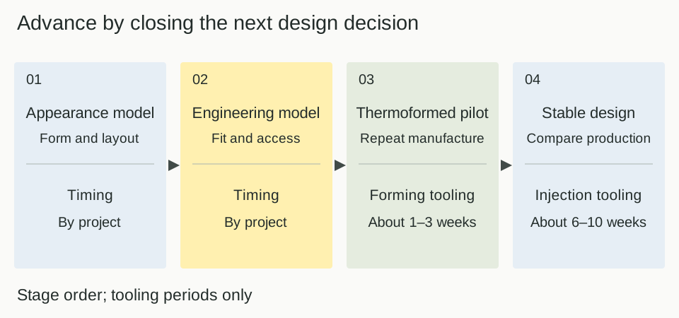
Use four stages to decide what evidence justifies investment
Select a process for the question that needs closing next. An appearance model tests proportions and access; an engineering prototype tests assembly; a thermoformed pilot checks repeated manufacture; a stable-design check tests the case for injection tooling. Enter quantities from the actual validation plan and purchase releases rather than assigning a universal batch size to each stage.
| Stage | Quantity | Process | Period | Key decision | Condition for the next stage |
|---|---|---|---|---|---|
| Appearance model | As appearance validation requires | Industry methods: 3D printing or CNC model machining | Confirm by project | Proportions, operation and service access | Appearance and layout review closed |
| Engineering prototype | Per assembly-validation plan | Prototype methods with forming review | Confirm by project | Frame datums, interfaces and component list | Critical interfaces and assembly method agreed |
| Thermoformed pilot and low volume | Per pilot and purchase releases | Heavy-gauge thermoforming and CNC finishing | Thermoforming tooling about 1–3 weeks | Wall, fixtures, inspection and delivered cost | Sample, measurement and repeat-supply plan approved |
| Stable-design production review | Per cumulative purchase plan | Compare injection molding with the current route | Comparable injection tooling about 6–10 weeks | Lifetime cost, revisions and transition | Interfaces validated and investment plan approved |
Use early models to settle form and equipment access
Industry prototype methods include 3D printing and CNC model machining. They can explore curvature, display placement, sensor openings and service clearance while the shape is changing. Unit effort depends on the geometry and finishing required. Define what the model must demonstrate before ordering it, and distinguish an appearance decision from validation of the eventual production process.
Give engineering prototypes a controlled assembly baseline
An engineering prototype should establish the frame coordinates, mounting datums and component list. Changing local features can remain prototype work while the team checks forming directions, splits and machining access. Spending at this stage covers models, modifications and assembly checks; the condition for moving forward is closure of changes that would disturb the locating scheme.
Keep a configuration record that connects each shell identifier to the frame revision, drawing and sample purpose. Distinguish a model used for a styling decision from a part released for assembly comparison, even when their outside surfaces look similar. When a supplier proposes a different split or locating surface, update that record and identify the mating parts affected. The roadmap's quantity field can then refer to the validation work actually planned, while a purchasing release refers to the approved configuration. This makes later samples useful evidence of progress instead of a collection of visually similar parts with different interfaces.
Check repeatability with the thermoformed pilot
Review tooling, trim fixtures, inspection and protection as one delivered-part proposal. FUNYO heavy-gauge tooling takes about 1–3 weeks; comparable injection tooling takes about 6–10 weeks. Those are tooling periods. Ask separately what a contour change and a relocated CNC opening would alter, so purchasing can see the work behind each revision quotation.
Reprice the investment when the design is stable
Stable geometry and a credible cumulative purchasing plan support a review of fixed investment. FUNYO heavy-gauge tooling costs less than 1/10 of comparable injection tooling for the same part scope; that comparison concerns tooling fees only. Put samples, fixtures, finishing, assembly and transport into separate quotation lines before comparing delivered cost and revision exposure.
Put assembly and service access ahead of the split line
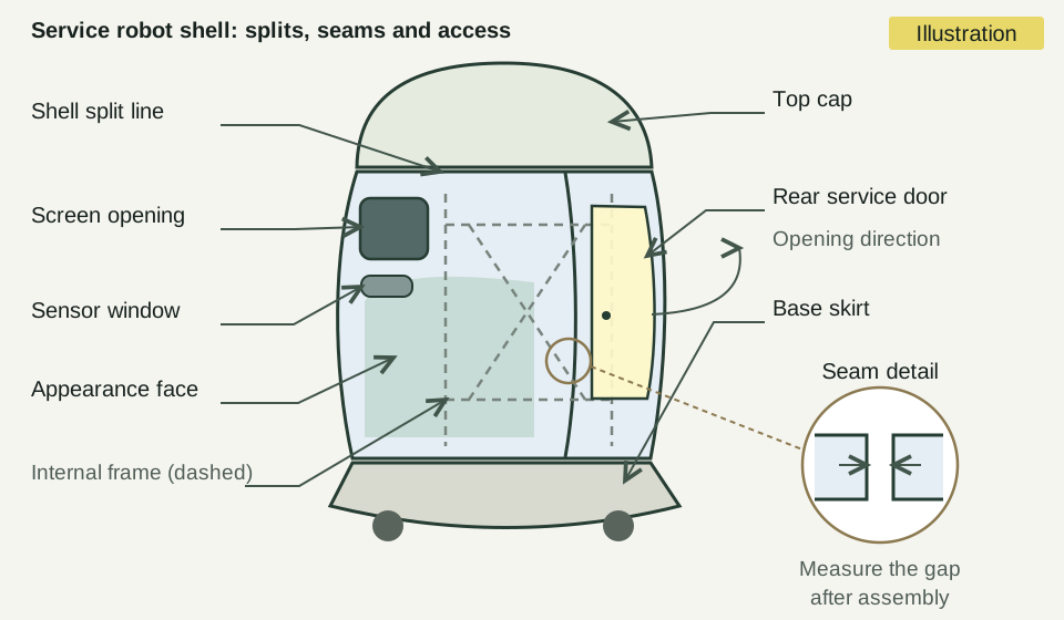
Draw splits around assembly order, removal direction and the visible surfaces that must align. A service panel and a comparatively stable styling surface can have different release and replacement needs. Show adjacent shells, internal supports and the tools used for maintenance in the assembly model, so the seam is compared as part of the equipment.
The assembled gap depends on each shell, its support points and the installation sequence. Specify datums, adjustable locations and acceptance condition, distinguishing a loose part from a shell installed on its frame. For screens, doors and sensor windows, tie the controlled fit to the relevant locating surfaces and machined edges.
Choose male or female tooling according to the important surface and dimensional relationship. Check tool detail, sheet texture and free-side variation together, then examine deep corners and finished wall. A narrow pocket created by the split may justify a separate panel or a different interface. The heavy-gauge design guide explains the drawing review.
Painting and other coating are confirmed by project. List the appearance target, coverage, color reference and sample approval method separately in the RFQ. Distinguish a sheet texture from a tool-produced texture and show its direction on the appearance drawing. Ask suppliers to state the delivered condition; approve samples against the same appearance reference.
Give the frame, cover and insert separate responsibilities
Define the load path and assembly datums before assigning functions to shells, brackets and inserts. The cover can establish an appearance and access boundary, while a frame locates equipment and an insert supports its specified contents or contact areas. When a styling panel changes, those boundaries help the team identify which internal relationships need to change.
List bosses, clips and attached hardware individually in the assembly plan. Draw tool access, cable clearance, removal order and load transfer in section. Identify what the cover carries and what an independent bracket carries. Confirm the heavy-gauge connection arrangement and supplied scope by project, using a component list alongside the appearance model.
FUNYO performs heavy-gauge thermoforming, thin-gauge thermoforming and CNC machining in-house, from design and tooling to production shipment. Heavy-gauge shells, thin-gauge inserts and machined features can therefore be discussed in one interface review using common assembly coordinates, drawing revisions and approved samples. Define the insert's actual function and acceptance conditions in that review.
Its 3-axis and 5-axis CNC work includes tooling, trimming, deburring, holes and slots. Separate the formed blank from the finished component, and show how the locating fixture reproduces the equipment datum. For an opening or edge relationship crossing several shells, record both the part datum transfer and the assembled inspection so a revision can be assessed consistently.
Use a service walkthrough to check the internal arrangement before approving the shell set. Check the route used to remove a panel, where an operator supports it, and which cables or nearby components remain connected. A bracket that is accessible on an open frame may be hidden after the neighboring cover is installed. Record that sequence in the assembly information and identify the supplied condition of any separately installed parts. Carry the same sequence into sample approval so that a dimensional check and a practical removal check address the actual equipment arrangement.
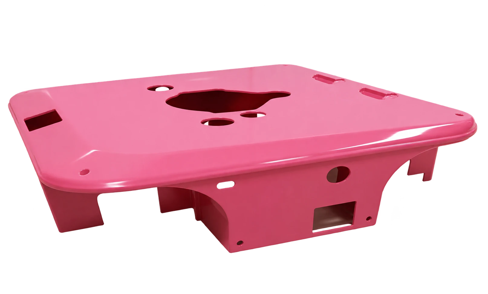
The photograph marked Reference shows a comparable product form; it is not a FUNYO delivery case.

Decide when to change process using matched costs and datums
Compare new investment, delivered unit cost and the purchases still relevant to the current design. Tooling and fixture costs are allocated across production quantity. Separate reusable tools, fixtures and inspection work from new expenditure when comparing the next stage, especially where a mature prototype program has already absorbed development work.
Use the thermoforming versus injection-molding break-even method to match trimming, openings, appearance and packing before inserting fixed and unit costs. Include revision work and the saleable life of the design. A proposal based on a stable lifecycle deserves comparison with the same lifecycle, rather than a changing forecast or a different finish scope.
Preserve frame coordinates and mounting relationships through the process change, then redefine the new part's shrinkage, draft and tolerance arrangement. Validate the engineering sample with the existing mating components before agreeing drawing freeze, stock transition and release timing. A new appearance contour can be acceptable while the common interface remains the basis for approval.
Plan how old and new shell revisions will be identified during the transition. Ask whether they share the same mating parts and which service replacements remain applicable. Record the approved combinations in the component list, and align the purchase release with that decision. Keeping the equipment configuration traceable is part of comparing the transition proposals, alongside tooling and unit cost.
Housing projects with annual demand of about 3,000 pieces and an annual supply agreement can apply to FUNYO for a tooling-fee waiver evaluation. Include release plans, revision expectations and the supplied scope, then record the evaluation in the quotation and agreement. Discuss tooling ownership, changes, storage and future use alongside the commercial proposal.
When does a robot housing merit an injection-molding review from the start?
A small housing with concentrated internal detail, mature geometry and a stable purchasing plan can justify comparing injection molding early. Dense clip and boss arrangements put integration and long-term cost into the same decision. If load carrying, electrical bonding or shielding dominates, check the corresponding frame and other manufacturing routes alongside the appearance cover.
Use the function and purchase plan as the decision basis. Request quotations for the same assembled state, then ask whether the sample demonstrates the critical interfaces, appearance and service actions. This keeps investment attached to evidence that closes the next project question and gives a reason for continuing or changing the route.
Send the version, interfaces and stage objective with the inquiry
Prepare shell models, the frame assembly, proposed splits, critical gaps, current prototype status and the purchasing plan. Mark the decision this order should resolve and the conditions for moving to the next stage. Identify owners and decision dates for changing surfaces, openings and mounting relationships, so the reply can address the open work.
Check the robotics application page, covers and shrouds and equipment housings. Send the roadmap with the same drawing revision and ask for tooling, machining, appearance and inspection responsibilities. Compare the stage proposals only after their delivered-part boundaries are clear.