Cosmetic acceptance starts with the surfaces visible after assembly, then defines lighting, viewing distance, observation time and defect limits for each zone. Webbing, chill marks and whitening describe different effects of sheet movement, cooling or stress. Record where the mark occurs and how the part is supported before deciding whether the response belongs in the design, forming process, trimming operation or handling method.
Define A, B and C surfaces around the installed product
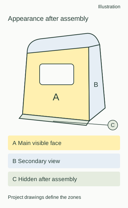
An A surface can be the main face seen during normal operation, a B surface a secondary or occasionally visible face, and a C surface an area hidden after assembly. These are project categories: the drawing must show their boundaries. A front cover, sidewall and mounting flange can have different appearance requirements while belonging to the same formed shell.
Use the assembly view to explain the observer's direction. An internal wall exposed only when a service door opens has a different viewing condition from a broad front panel. Extend the zone boundary to an identifiable radius, seam or edge. A note such as acceptable appearance leaves much more interpretation than a marked surface map and an approved comparison sample.
Function remains a separate acceptance question. A burr on a concealed flange can interfere with installation or damage a contacting component. A slight texture change on a visible face calls for comparison under the agreed visual conditions. Give appearance, fit and edge contact their own requirements so an inspector can record each result against the correct purpose.
Diagnose webbing, chill marks and whitening by their mechanisms
Describe the observed shape before naming the cause. A shiny patch, pale region and folded ridge may require different responses even when a photograph makes them look similar. Mark the tool-contact direction, nearby features and finished trim line on the drawing. Keep the original sample available while comparing its surface, section and relationship to the assembly.
Webbing begins when excess sheet folds between features
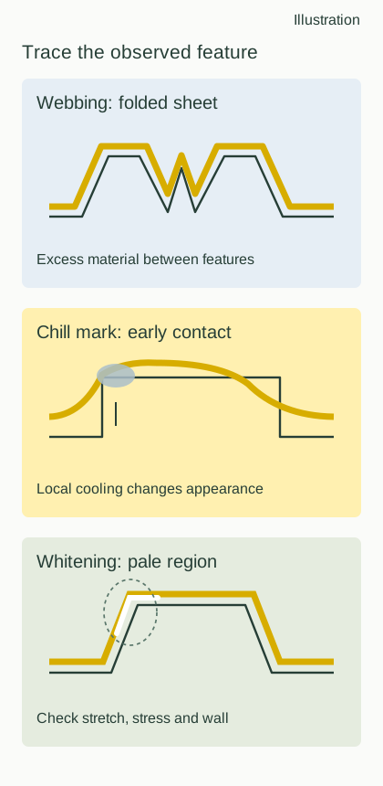
Webbing is folded material accumulating between adjacent raised features. Closely spaced forms, abrupt height changes or a restricted path into a recess can let sheet contact the surrounding tool before the remaining material has somewhere to go. Design options include greater feature spacing, broader transitions, a different forming orientation or splitting the cover into separate parts.
Photograph the root of the fold with both neighboring contours. Identify whether it crosses an attachment face or visible seam. A design response should change the material path rather than simply remove the raised appearance after forming. If a residual impression is acceptable, its location and boundary belong in the approved sample and acceptance record.
Chill marks follow early contact and local cooling
A chill mark is a local appearance change associated with sheet contacting a cooler surface early in the forming sequence. A projecting feature or sharp transition can interrupt the stretching path: one area cools while adjacent material continues to move. Discuss radii, forming direction, heating distribution and contact order together when diagnosing a repeated mark.
Check whether the location follows the same feature across samples and mark it on the contact-face drawing. A broader transition or a revised approach to the tool can change which area touches first. Retain the sheet grade, surface orientation and tool condition with the sample so a forming mark can be distinguished from the sheet's original gloss pattern.
Whitening needs both a surface record and a thickness check
Whitening is a local change toward a paler appearance and can accompany stretching, stress or bending during handling. Deep corners and areas contacting the tool late deserve attention. Relate the pale region to wall measurements and the surrounding shape. A surface decision should account for the part's support, attachment and service role as well as its color.
If the mark appears after removal or transport, examine the gripping and bending locations. Fixtures, packaging contacts and installation forces can produce marks through a different path from forming. Record the stage where it first appeared. Any rework proposal should also explain how wall condition and fit will be checked after the visible mark has changed.
Texture, cut edges, warpage and handling marks need different checks
Texture distortion should be compared in the same orientation. Changes in depth stretch the sheet pattern and change reflected light; sheet texture direction, transitions and the contact face therefore belong on the drawing. For neighboring covers, compare the texture across the assembled seam rather than judging only the middle of an isolated panel.
For burrs and chipped edges, inspect cutouts, slot ends and the completed perimeter. Tool path, entry and exit positions and support during cutting can affect the finished edge. State how that edge contacts the user or adjacent component and identify the required deburring condition. Machining and inspection should refer to the same finished outline.
Warpage must be judged with the specified supports and part condition. A freely resting shell and a cover attached to a frame can present different shapes. Scratches and dents instead call for a contact history: stacking, separators, fixtures and packaging supports. Direct protection toward the assigned appearance faces, and retain records of where the handling contact occurred.
Write viewing conditions before assigning defect limits
Lighting and viewing conditions are agreed for the project. Specify the light source and direction, part orientation, viewing distance, observation time and permitted movement. If magnification is used, define its purpose separately. Searching for loose particles on a washed tray and judging the overall gloss of a machine cover involve different observations and acceptance objectives.
Each defect limit should identify its type, size, count, location and any clustering restriction. A location map defines what edge area or central area means. Record sizes with the agreed method, and specify a method for color or gloss where those characteristics matter. Accepted and rejected boundary samples then give inspectors a common reference for applying the written limits.
Also state whether the part is clean, covered by protective film, freely supported or installed. A mark found through packaging and a mark created during assembly can have different origins. Record the discovery stage, packaging condition and sample identity. Those details connect a corrective action to the operation that can actually change the result.
Use one table for defect definitions and surface-zone limits
Give each row one observable condition and fill the A, B and C limits separately. The empty limit cells below are for the buyer and supplier to complete against the drawing and samples. Adjust inspection conditions and decision methods for the actual product, then identify the approved table revision in the purchasing documents.
| Defect | Definition | A-surface limit | B-surface limit | C-surface limit | Inspection conditions | Decision method |
|---|---|---|---|---|---|---|
| Webbing | Folded sheet between adjacent raised features | Identify the zone and viewing direction | Compare with the approved boundary sample | |||
| Chill mark | Local gloss or contact change after early cooling | Use the same light, orientation and surface state | Compare the location map and boundary sample | |||
| Whitening | A locally paler surface region | Record discovery stage and wall-measurement points | Judge appearance and wall condition separately | |||
| Texture distortion | Change in pattern spacing or direction after stretching | Align texture and viewing directions | Compare in the assembled condition | |||
| Burr or chipped edge | Residual material or missing material at a finished edge | Cover holes, slot ends and the perimeter | Apply edge requirements and approved samples | |||
| Warpage | Shape departure under the specified support condition | Define support, placement and temperature condition | Record shape and assembled gap separately | |||
| Scratch or dent | A surface mark from contact or pressure | Record packaging and contact zones | Apply zone, size and count limits |
Download the cosmetic acceptance template to enter the agreed limits and approval information. Use Large-Part Thermoforming Tolerances: Drawing Guide when defining support and inspection conditions. Keep visual acceptance and dimensional results in separate fields so a passing appearance decision does not conceal a fit issue.
Control boundary samples by revision and storage condition
A boundary sample is an agreed reference for the acceptance threshold. Register its material, color, texture, appearance zones and viewing conditions. Mark the relevant location and direction, and photograph it from a repeatable angle with a scale where useful. An acceptable boundary and a clearly rejected condition can explain where the decision changes more effectively than a general description.
Protect samples from rubbing, contamination, light exposure and stacking that could change the feature being judged. Keep a record of condition when a sample is taken out and returned. Photographs support traceability, while reflections, exposure and screen rendering can alter the apparent result; the approved physical comparison method remains part of the specification.
When the drawing, material, tool surface or production route changes, decide which boundary samples still represent the part. A change record should identify retained requirements and items requiring new approval. Preserve the old sample's revision identity. Production receiving should use a consistent combination of drawing, acceptance table and approved sample rather than documents from different releases.
Separate FUNYO tray inspection from heavy-gauge finishing
方宇(FUNYO) includes full visual inspection and magnified sampling in its thin-gauge tray cleaning sequence. Washed thermoformed trays are checked at 20× magnification, and any loose particle triggers a search for the contamination source. These are thin-gauge tray operations; the order should identify the surfaces, foreign-matter criteria and packaging contacts relevant to the project.
For trays and other small or medium components, dimensional discussions can use the Nikon VMR-6555 automatic vision measuring system and VMS-5040 optical 2.5D system. Dimensional records, particle observations and appearance photographs serve different purposes. The Quality Assurance page describes the equipment and record categories that can be connected to an order's inspection scope.
Heavy-gauge finished edges are addressed through 3-axis and 5-axis CNC trimming, deburring, holes and slots, with acceptance against the drawing and agreed samples. FUNYO evaluates ABS, PC, PVC, PETG and PP sheet. Provide color, texture and contact requirements with the material request; Thermoforming Materials Guide: ABS, PC, PVC & PP helps organize those questions without treating a polymer name as a complete appearance specification.
When should coating, film or injection molding be compared first?
Broad mirror-gloss surfaces, very small visible variations across a continuous face or complex internal features justify comparing another manufacturing route before tooling starts. Coating, film and injection molding change how the final surface is created. Each introduces its own material, finishing and acceptance conditions, which belong in the same RFQ scope used for the thermoformed proposal.
Retain the same assembly view, appearance target and defect limits while comparing routes. Edge coverage, cutouts, color consistency and repair methods still need definition when a surface treatment is proposed. Start geometry discussions with Heavy-Gauge Thermoforming Design: Draft and Walls: resolve transitions, spacing and contact direction before assigning the remaining appearance requirement to another operation.
Send the zone drawing, marked sample and acceptance table together
An RFQ should include the assembly view, A/B/C zones, sheet and texture requirements, marked photographs and proposed viewing conditions. When investigating rejected parts, retain the original packaging state and discovery stage. Identify whether the concern affects appearance, assembly or contact safety so the sample work targets the right feature.
FUNYO responds within 4 hours and provides a suitability assessment and comparison quote within 2 working days. Use the proposed route to define forming, finishing, protection and inspection in one specification revision. Approval of the sample and its boundary references then gives subsequent receiving inspections a repeatable basis for deciding whether the delivered part meets that agreed condition.