Define the tray by the handovers it must support
Specify a large thermoformed handling tray by its locating method, load path, stack arrangement and handling interfaces before choosing sheet material. The tray must hold the part and present it consistently to the next person or machine. Heavy gauge is an option for medium-to-large parts with annual demand from hundreds to a few thousand pieces, the application range described by 方宇(FUNYO).
For transfer between processes, start with the part orientation and the handover at each station. Mark the permitted contact surfaces, protected areas and pickup direction on a section through the loaded tray. A support surface carries weight, while a locating feature controls movement. Identifying these roles helps the forming and handling proposals address the same task.
A line-side tray also has to fit the loading sequence. Include operator access, gripper entry and the space needed to lift or turn the part. Show the condition after neighbouring pockets have been emptied as well as the fully loaded condition. This reveals whether the intended sequence remains practical throughout use.
Inter-plant transport adds packing, restraint and return requirements. Record the receiving equipment and the empty-tray return method alongside the delivery route. The interface information on the EV and energy industry page and packaging and material handling page can help organize the discussion, while the actual station drawings define the project.
Separate the outside envelope from starting sheet gauge
The outside envelope defines occupied space; starting gauge identifies the sheet used to form the tray. FUNYO's maximum heavy-gauge part size is 2600 × 1600 × 600 mm (102.4 × 63.0 × 23.6 in), with a working starting-gauge range of 6–15 mm (0.24–0.59 in). Show both on the drawing, together with the locations where finished-wall measurements matter.
Separate the tray envelope from the loaded-part envelope. A rack, aisle, workstation or shipping package may constrain a different direction. Include the loaded assembly and the usable space around it, with keep-out areas marked. Photographs help explain the setting, while a dimensioned interface drawing establishes what the design must clear.
FUNYO's heavy-gauge work includes large new-energy trays of 2,500 × 1,100 mm (98.4 × 43.3 in). A new project still starts from its own contact locations, forming depth and handling supports. Similar outside dimensions can conceal very different load paths, pocket arrangements and return requirements.
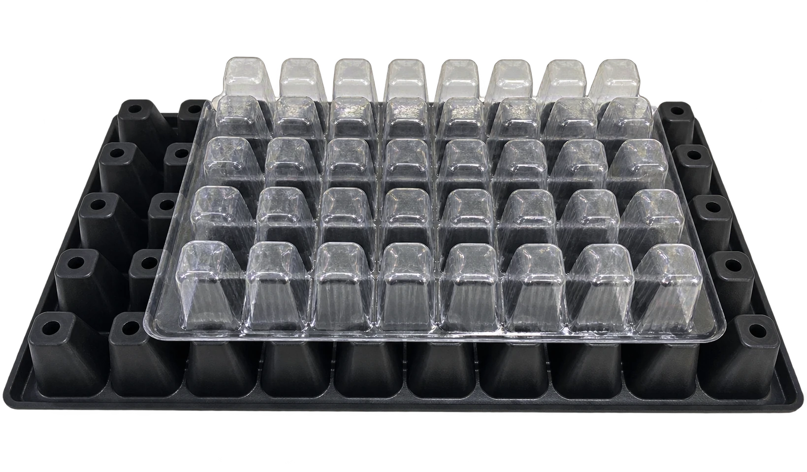
Starting gauge and formed-wall thickness belong in separate drawing fields. Material stretches around the cavity and its transitions, so the finished distribution varies with geometry. Record the supporting condition and the measurement locations on the sample drawing. Those records let the team connect a wall measurement with what happened during loading or stacking.
FUNYO uses 3-axis and 5-axis CNC for tooling, trimming, deburring, holes and slots. Send the formed outline and the finished machining outline together. Mark which edges locate the tray, which openings provide access and which features connect to other components. Tool access and fixture support can then be considered before the trim boundary is approved.
Carry the load through ribs and feet to the real support
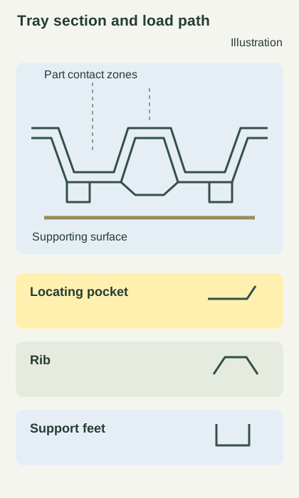
Load design follows the force from the part contact zones into the tray and then into the workstation, rack or handling device. The same part weight can produce different local demands when its contact area, offset or bottom support changes. Discuss the loaded assembly and the supporting structure together instead of comparing sheet gauges alone.
Ribs should connect the working contact zones to the intended supports. Feet establish where the tray transfers load to the surface below. Show their contact faces, handling clearances and landing positions on the section. This makes it easier to see whether a proposed support conflicts with a fork entry, a moving clamp or the empty-return arrangement.
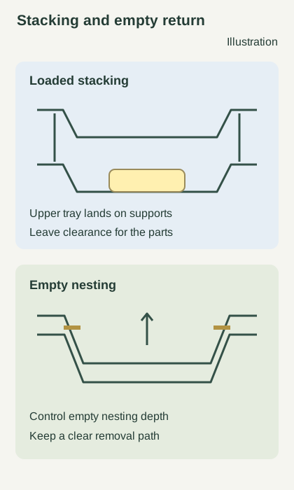
Loaded stacking and empty nesting solve different problems. A loaded stack needs defined landing zones and clearance for the parts. Empty nesting needs a controlled nesting depth, access for separation and a suitable grip. Draw both conditions, including the direction in which an empty tray is removed, before agreeing on the storage and return arrangement.
Validate samples with the planned part, orientation and handling supports. Observe contact marks, deformation, stack position and the loading motion. Record where an observation was made and relate it to the sample revision. A change to a rib, foot or contact face can then be followed into the next sample and the eventual receiving criteria.
Give locating pockets and inspection datums separate jobs
Locate the part from its functional datums, then identify the surfaces that support weight and protect appearance. Mark what controls movement in each relevant direction and where clearance is intentional. Following the complete outside shape closely can make loading or removal harder when the incoming part and the tray both vary.
Divide dimensions into overall envelope, locating pockets and machined interfaces. Overall dimensions relate to the rack or station; pocket dimensions relate to the part; holes and slots relate to attachments or assembly. Put the measurement direction and supporting condition beside the relevant view so both parties can reproduce the same inspection.
Free-state measurement and measurement under working support answer different questions. Try the sample with the actual part to assess stable location and removal. For recorded dimensions, use the agreed datum and support procedure. Keep the drawing, fixture description and inspection sheet connected to the same revision so dimensional findings can explain handling performance.
Use Large-Part Thermoforming Tolerances: Drawing Guide to separate tool-contact, free-surface and CNC features. The Heavy-Gauge Thermoforming Design: Draft and Walls guide helps organize sections and machining boundaries. Large heavy-gauge trays require acceptance criteria developed for their own geometry and support conditions.
Choose a sheet grade against the contact and service conditions
Material selection begins with the part, the operating environment and the reuse plan. FUNYO evaluates ABS, PC, PVC, PETG and PP sheets for heavy-gauge work. Identify the proposed grade, surface condition and starting gauge in the RFQ so samples and later deliveries refer to the same material specification.
List oils, coolants, cleaning agents and temperature conditions separately. Describe extended storage, repeated washing and transfers between environments where these affect use. The supplier can then provide grade information for the project team to assess and decide which contact, appearance and loaded-use trials are needed. Keep the conditions of those trials with the results.
ESD and flame-related material requirements are confirmed by project. For ESD, state the component being protected, test conditions and acceptance basis rather than relying on tray colour. Thermoformed Automation Trays: Tolerances and ESD explains the purchasing questions. Select the large tray's actual material and sample against its own handling environment.
Cleanliness should also identify a contact surface and a point in the handling route. Explain where contamination could affect the next process, how the tray will be cleaned and what is inspected during reuse. Agree the packing and storage protection around those requirements. This connects material selection with the maintenance work that operators will actually perform.
Compare tooling, finishing and handling interfaces on the same basis
Compare thermoformed trays, injection-molded trays and metal racks against the same locating and handling task. FUNYO's heavy-gauge tooling takes about 1–3 weeks, compared with about 6–10 weeks for comparable injection tooling. These periods concern tooling. Drawing approval, sample validation, changes and transport each need a separate place in the project schedule.
FUNYO heavy-gauge tooling costs less than 1/10 of comparable injection tooling for the same part scope. That ratio concerns tooling fees only; delivered unit cost and project cost are calculated separately. List CNC trimming, attachments, packing, inspection and freight as distinct scope items, then use Thermoforming vs Injection Molding: Break-Even Cost to compare matching inputs.
An injection-molded proposal should explain its complete structure and long-term supply arrangement. A metal-rack proposal should explain its frame, joints and site interfaces. Send both the same loaded positions, stack arrangement, route and reuse requirements. Compare sample behaviour, maintenance and replacement scope alongside the quotation to understand the source of each cost difference.
Annual demand from hundreds to a few thousand pieces is an initial heavy-gauge application description. The purchasing decision also depends on pocket changes, part revisions, replenishment and the expected use cycle. Identify which changes affect the tooling, the tray body and the external interfaces separately. This makes later adjustments easier to price and approve.
Put the part, handling and supply conditions in one RFQ
The RFQ should cover the carried part, the tray's interfaces with site equipment and its repeated-use conditions. Fill the checklist with project information and use matching revision identifiers on the part, interface and packing drawings. Where information comes from different departments, identify who supplies it and who approves it in the project record.
| Item | What to supply | Project response |
|---|---|---|
| Part dimensions and weight | Attach the part drawing, weight and handling orientation | |
| Parts per tray | State the quantity per tray and any mixed-part restrictions | |
| Locating method | Mark contact zones, keep-outs and the loading direction | |
| Stacking levels | Separate loaded-stack requirements from empty-tray return | |
| Handling method | Identify forklift, AGV or manual handling and attach interface drawings | |
| Envelope limits | List aisle, workstation, rack and packaging restrictions | |
| Material and ESD | List candidate sheets and material requirements to confirm | |
| Cleanliness | Identify contact surfaces, contamination risks and acceptance methods | |
| Reuse cycles | Describe repeated use, cleaning and inspection plans | |
| Annual demand | Separate the first order, annual demand and replenishment pattern |
Download the large-tray specification checklist, complete the known conditions and bring the remaining design decisions into the supplier discussion. Update the checklist when the part or workstation changes. The quotation should continue to refer to the same geometry, handling conditions and delivered scope as the current drawing set.
When should injection trays or metal racks be assessed first?
Assess injection molding first when locating functions rely on complex internal geometry and the design and supply plan are mature. Compare long-term supply, finishing, assembly and maintenance as a complete proposal before accepting the tooling investment. A quotation and a sample built around the same delivery scope provide the decision basis.
Assess metal racks or a combined structure when the main task is joining an existing metal frame, repositioning supports or accommodating a specialized handling device. A tray can provide location and protection while the frame handles its intended structural tasks. Divide responsibilities at their interfaces and compare that arrangement with an all-tray proposal.
Send the loaded assembly and handling interfaces together
The next step is to send the part drawing, loaded assembly, handling interfaces and completed checklist together, with the scope to be compared. FUNYO responds within 4 hours and provides a suitability assessment and comparison quote within 2 working days. Actual use conditions allow forming, CNC work and sample validation to be discussed together.
Check the product scope on the Trays and Liners page, then put sample acceptance in the project plan. Keep separate records for location, loading, stacking and removal. Once approved, tie the drawing, material and inspection method to the supply revision so later changes can follow the same record.