Fasten a thermoformed housing by defining the load path first, then choosing the locating surfaces, hardware and access needed for removal. A smooth shell can provide the cover while a frame, separate mounting pads and machined openings provide the attachment system. Review the complete joint before choosing a screw: the plastic, support, threaded component and installation method all affect whether the assembly stays aligned through service.
A single forming tool changes where attachment features belong
Thermoforming controls the surface against one tool, so small bosses and complex integral clips usually move into separate components or the equipment frame. Heated sheet stretches around the shape, leaving different finished thicknesses on broad faces, deep corners and late-contact areas. An injection-molded attachment arrangement therefore needs a fresh section drawing when it becomes a formed shell.
Show where the screw enters, which component holds the thread and which surface takes the clamp load. A clearance hole can locate the opening without carrying the thread. A nut in the frame supplies reusable threads, while a backing plate spreads contact pressure. Separating these functions gives the designer more useful choices than adding a boss to the outer-surface model.
Starting gauge and finished attachment thickness also need separate treatment. 方宇(FUNYO) evaluates heavy-gauge sheet up to 15 mm (0.59 in), with housings commonly starting at 8–10 mm (0.31–0.39 in). Measure the formed wall at the proposed joint before approving the support and fastener. The stock sheet value alone leaves the local stretching out of the decision.
The assembly sequence belongs on the drawing as well. Captive hardware needs an installation route before the enclosure closes. A separate bonded pad needs space for preparation, positioning and curing. Use the heavy-gauge thermoforming design guide to coordinate the attachment with draft, corner transitions and the final trimmed edge.
Compare fastening methods as complete joints
Choose a fastening method for its service access and load path, then compare how the surrounding structure supports it. The qualitative ratings below help screen industry options; actual capacity depends on the material, geometry and assembled condition. State the operations requested from FUNYO in the RFQ so purchasing, hardware installation and bonding have an explicit project scope.
| Fastening method | Suitable use | Repeated disassembly | Load capacity, qualitative | Processing method | Points to check |
|---|---|---|---|---|---|
| Direct self-tapping screw | Supported covers with light loads | Limited, subject to sample results | Low | Machine a pilot hole after forming and drive the screw | Local wall, hole size and clamp distortion |
| Rivet nut in the frame | Attaching a shell to a metal frame | Yes | High | Install the rivet nut in metal; machine a clearance hole in the shell | Frame thickness, grip range and resistance to rotation |
| Blind rivet | Lap joints opened infrequently | Remove the rivet to separate | Medium | Drill the supported overlap and set the rivet | Backing support and a repair route |
| Heat-set or ultrasonic insert | Added pads or sufficiently substantial attachment regions | Yes | Medium | Prepare the seat and install to the insert supplier's instructions | Resin compatibility, local wall and support |
| Bonded pad or adhesive stud | Keeping the visible shell surface continuous | Screw removable; bonded pad remains | Medium | Prepare, locate, bond and cure the separate pad | Adhesive compatibility, environment and peel loading |
| Separate clip or spring fastener | Light-duty covers opened for service | Yes, after joint validation | Low | Fit a separate clip or a spring feature on the frame | Release direction, wear and concentrated stress |
| Metal bracket or frame | Loaded interfaces and recurring maintenance | Yes | High | Mount the bracket to the frame and machine shell openings | Route loads around thin corners and flexible surfaces |
| Latch and hinge | Access doors and opening covers | Yes | Medium | Fit supported hardware after forming | Opening clearance, stops and backing plates |
The ratings compare joint concepts, rather than assigning a load rating to an individual screw. A frame-mounted rivet nut sends thread forces into metal, but excessive clamp pressure can still deform the plastic around its clearance hole. Draw tension, shear, peel and vibration paths through the entire section and select the hardware against its manufacturer's instructions.
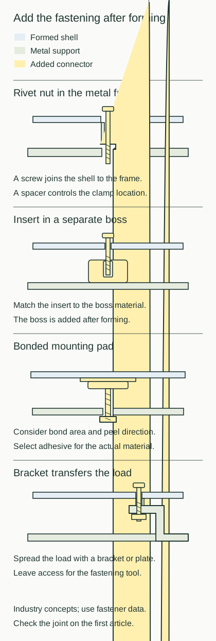
Removal also means different things for different joints. A bonded pad can remain attached while a service screw is removed. A riveted overlap needs a practical method for removing the rivet and restoring the joint. Walk through installation, maintenance and end-of-life separation before committing to the fastening layout.
Place attachments away from deep corners and check clear edge distances
Put mounting points in supported regions with more stable wall distribution, away from deep corners and areas that stretch late in forming. A flat clamping land helps the hardware seat consistently. Pulling a curved panel hard against a mismatched frame can convert an alignment problem into a visible depression around the screw.
For heavy-gauge housings, a hole-edge starting point is a clear distance of at least 2× starting gauge from both the trim line and the start of a radius, confirmed on the first article. This dimension runs from the edge of the hole. Include the hole radius when reviewing a drawing dimension measured from its center, and mark where the corner transition begins.
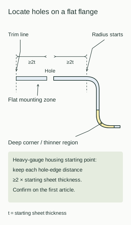
Compare ribs, returned edges, separate pads and backing plates according to the work each performs. A formed rib or return changes geometric stiffness; a backing plate spreads the joint's contact load. Review either approach with the actual formed wall. Mark the support footprint and clamping land so the sample inspection covers more than hole diameter.
Near a window, large opening or exposed edge, draw the washer footprint and tool clearance before fixing the hole position. Moving a joint into a better supported region may offer a simpler manufacturing route than adding more fasteners along a narrow edge. Revisit the adjacent bracket, cable path and removal direction whenever that position changes.
Use reusable threads for service and let the frame take structural loads
Repeated service favors metal threads and a frame or bracket that carries sustained loads. Repeated self-tapping into plastic changes the engaged material and makes consistent clamping harder to reproduce. Evaluate thread durability, anti-rotation and the plastic contact surface together, including what happens after the cover has been removed and installed again.
Trace the force from the point of use to the equipment support. A handle, hinge or impact point can turn an apparently light cover attachment into a bending load. Where the cover primarily provides appearance or protection, take the main handle or hinge force into the frame and use a controlled clamping surface to retain the shell.
The attachment arrangement should also accommodate dimensional variation and movement in service. Define the locating feature, then decide which remaining joints need clearance in a particular direction. Size those clearances from the material, temperature range and assembly geometry, and show the permitted motion on the drawing rather than leaving it to the installer.
Try the maintenance sequence with a physical mock-up or sample. Check tool entry, loose hardware, access to a damaged pad and the path of the removed cover. Recording these actions helps distinguish a joint-design problem from an installation-method problem and gives production a repeatable assembly sequence.
Reference CNC holes to the same datums used by the frame
Locate post-formed holes and trim profiles from the assembly datums so the shell and frame are inspected in comparable conditions. FUNYO uses 3-axis and 5-axis CNC for tooling, trimming and deburring, holes and slots. Specify the machined features, tool approach and support condition alongside the finished-part drawing.
A functional datum scheme might locate height from a base edge, depth from a seating face and lateral position from a locating feature. Connect the installation holes to that scheme. A flexible shell measured free on a bench can read differently from the same shell supported and fastened to the frame; define the inspection state in the large-part thermoforming tolerance guide terms.
Show the screw head, washer, mating thread and available depth in the section. A screw that reaches the bottom of a blind thread before its head seats can feel tight while leaving the cover loose. A washer that bridges a curved region can concentrate pressure at its edges. Check both conditions with the proposed hardware, and identify which drawing controls each contact surface. These details help purchasing preserve the joint when substituting an apparently similar screw or washer.
The finished edge is part of the interface. Tool access, support at the hole exit and burr removal affect how the hardware seats and how adjacent components survive installation. Distinguish locating holes, clearance holes and cosmetic openings on the drawing. The CNC machining capability page explains the relevant machining scope without assigning the same inspection requirement to every opening.
Validate the assembled joint before approving the fastening procedure
Sample validation should cover torque, pull-out behavior and repeated removal using the actual shell, hardware, backing and frame. Agree the direction of loading, support, tools and environment first. Set acceptance values from the project requirements and hardware information, then attach the results to the sampling and first-article checklist.
A torque record should identify tightening order and show the condition after clamping, including any local depression. A pull-out record should distinguish an insert leaving its seat, a pad debonding, plastic tearing and frame deformation. During repeated removal, record changes to threads, hole edges and the visible surface so the next revision addresses the actual failure path.
For a bonded option, keep the resin grade, preparation, bond-line condition, cure and service environment in the same record. Check material compatibility and a representative joint before testing the assembly. Retain hardware identification, drawing revision and photographs after approval. A later material or fastener substitution then has a clear list of affected checks.
When do numerous attachment features justify a different structure?
Compare a split structure or injection molding when the design needs dense small bosses, integral flexible clips and intricate internal locating features. A smooth outer shell can be separated from an attachment frame. If the objective is to combine those features into a single part, include tooling, secondary machining, hardware and assembly labor in the comparison.
Compare delivered parts that perform the same installation and maintenance tasks. The thermoforming proposal should state forming, openings, brackets and their installation scope; the injection proposal should cover the corresponding structure and secondary operations. Use the thermoforming versus injection molding break-even worksheet to examine quantity and revision effects after the functional requirements are aligned.
Send the joint sections and service requirements with the RFQ
An attachment RFQ needs the finished model, joint sections, frame interface, load directions and removal requirements, plus the current selection table. FUNYO's maximum heavy-gauge part envelope is 2600 × 1600 × 600 mm (102.4 × 63.0 × 23.6 in). Heavy-gauge forming, thin-gauge forming and CNC machining are performed in-house; list hardware procurement, installation and any bonding requested as separate project scope items.
Review the equipment housing product family and download the fastening selection table. FUNYO responds within 4 hours and provides a suitability assessment and comparison quote within 2 working days. Mark the joints to be validated on the assembly drawing so forming, machining and first-article approval can be discussed together.