A thermoforming sample should establish a repeatable agreement about the drawing, material, finished part and acceptance conditions. Heavy-gauge tooling takes about 1–3 weeks, while approval, changes and transport belong on separate schedule lines. Before authorizing tooling, define what the sample must demonstrate and who can release it for the next stage.
Freeze five inputs before the sample is made
Freeze the drawing revision, material and starting gauge, appearance zones, critical dimensions and measurement state, and sample quantity and purpose. These five inputs give the sample a defined job. Later changes remain possible, but the change record should identify which input moved and which part features or test results are affected.
Keep the model, dimensioned drawing and assembly drawing on the same revision. A model describes the contour; a drawing identifies controlled features; an assembly view explains location and neighbouring parts. If their openings or boundaries disagree, resolve that difference in the document list before the toolmaker and trimming programmer work from separate interpretations.
Material information should connect the proposed sheet with its color, texture and starting gauge. Finished-wall requirements belong at the relevant locations on the part drawing. Stretch during forming changes the local wall, so a starting-gauge entry alone cannot describe the finished corner. Mark the regions that matter to fastening, handling or contact with another component.
Define the sample's purpose as well as its quantity. An appearance reference, an installation trial and an operating trial may require different features, mating components and records. Identify the external faces visible after assembly, the locating surfaces and the state in which dimensions will be measured. That makes the approval task specific enough to assign.
Use Thermoforming RFQ Checklist: Scope and Drawings to organize the input package. 方宇(FUNYO) accepts STEP, IGES, DWG, PDF or photographs. Photos plus dimensions can start the discussion when a drawing is unavailable; turn that discussion into a controlled document list before manufacturing the sample.
Put tooling and sample approval on separate schedule lines
FUNYO heavy-gauge tooling takes about 1–3 weeks. Tool completion is a manufacturing milestone, followed by forming, finishing, inspection and the buyer's intended trials. The project schedule should identify the approved drawing that releases tooling and the physical parts or records required to release each later stage.
Thin-gauge tray tooling for parts within 500 mm (19.7 in) takes as little as 8 hours and typically 2 days. Carry that complete thin-gauge tray tooling condition into the plan. Quote a heavy-gauge housing and a thin-gauge tray as separate process requests so their tooling conditions stay attached to the correct part.
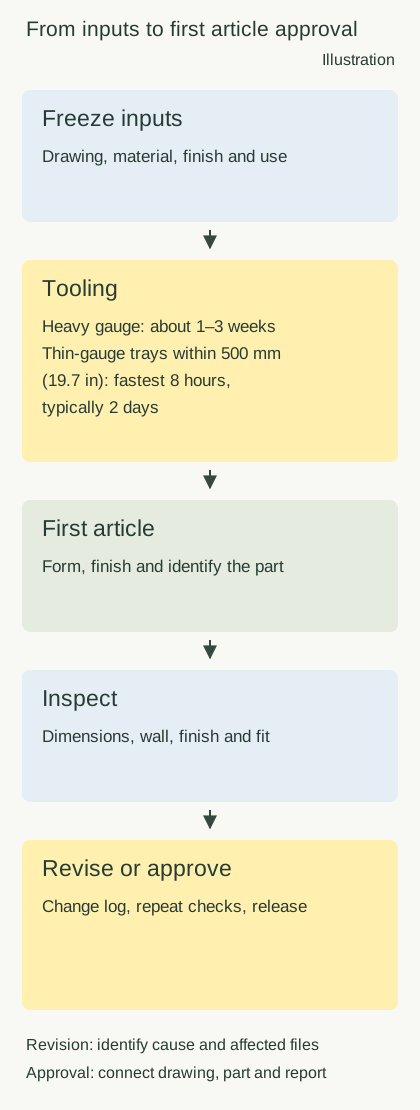
Approval needs the right components and people at the receiving end. Confirm where samples will arrive, which mating parts will be ready and who will consolidate comments. A set of photographs from separate departments is more useful when each observation identifies the same sample, feature and operating condition.
Schedule sample approval, revisions and freight by project rather than assigning an unsupported duration. State the required arrival date with the RFQ. The heavy-gauge capability page and thin-gauge capability page help separate the two routes before tooling and sample milestones are agreed.
Inspect dimensions in a defined state, then check the finished part
First article inspection should cover dimensions, finished-wall thickness, appearance, assembly and function. Each result needs a location and a condition. A freely resting contour and a hole measured after fastening answer different questions; recording the state makes the reading useful when a later sample behaves differently.
Identify datums, support points and clamping before recording dimensions. Include the fastening sequence where assembly loads change the contour. For a locating tray, show which edge contacts the fixture and which region carries support. Large-Part Thermoforming Tolerances: Drawing Guide explains how those conditions belong with the dimensional requirement.
Map wall measurements across flats, transitions, deep regions and functional contact areas. The sheet stretches along the forming path, leaving a distribution that depends on geometry as well as starting gauge. Keep the measurement map with the readings. Observe the relevant mounting or service operation where the wall must accept contact or repeated handling.
Judge appearance against the same zone map, observation conditions and limit samples. Record the type and location of an observation rather than a general statement that the finish is unacceptable. Use Thermoforming Defects: Webbing, Chill Marks & Checks to organize webbing, chill marks, whitening and finished-edge decisions, then connect approval to an identified reference sample.
Trial-fit the matching component revisions. Check mounting alignment, fit after fastening, cable and tool access, and the intended opening of service covers. Preserve those operations in the first article record even where the individual part dimensions pass. They define the practical assembly condition that a future revision must continue to meet.
Connect the first article report to the drawing and sample
The report should identify the drawing revision, sample, method, acceptance conditions and result. The following 18 checks form a project worksheet. Leave the result field blank until inspection, then enter the actual reading or decision and attach its measurement map, photographs or operating notes.
| Check | Method | Measurement or acceptance conditions | Record | Result |
|---|---|---|---|---|
| Drawing revision | Match drawing and model | Use the same approved revision | Drawing number, revision and date | |
| Sample identity | Match sample and records | Separate earlier and revised samples | Sample identifier and photographs | |
| Material and starting gauge | Check material documents | Use approved material and gauge requirements | Material identity and incoming record | |
| Overall dimensions | Measure to the drawing | Identify datums, supports and measurement state | Feature, reading and units | |
| Locating dimensions | Measure assembly-related features | Use the agreed locating method | Feature identifier and measurement record | |
| Holes and slots | Measure positions and openings | Use the finished-part drawing | Positions, sizes and photographs | |
| Trim outline | Compare the finished boundary | Locate from the agreed datum | Contour deviation and edge photographs | |
| Finished-wall thickness | Measure marked regions | Separate flats, corners and deep areas | Measurement map and readings | |
| Appearance zones | Compare the appearance map | Use agreed observation conditions | Defect location and photographs | |
| Color and texture | Compare the approved reference | Use the same observation conditions | Reference identity and decision | |
| Burrs and edges | Inspect contact edges | Use service and assembly requirements | Locations and disposition record | |
| Warpage and fit | Fixture in the operating state | Identify supports and fastening sequence | Gap locations and state photographs | |
| Mounting interfaces | Trial-fit mating components | Use matching component revisions | Assembly record and interference locations | |
| Service and removal | Follow the intended access path | Keep connections and adjacent parts in trial condition | Operation record and issue list | |
| Functional trial | Test the project application | Record load, environment and connections | Test conditions and observations | |
| Packing and protection | Check contact and separation | Use the approved packing arrangement | Packing photographs and identification | |
| Changed-feature checks | Remeasure affected features | Use the revised drawing and sample | Change record and repeat results | |
| Approval and retained sample | Sign the report and identify retention | Use the approved revision after issue closure | Approver, date and storage location |
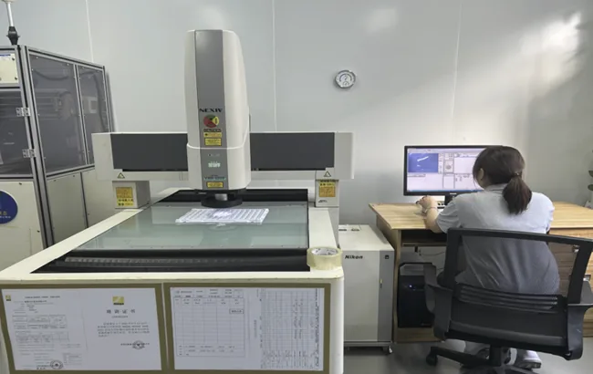
FUNYO has a Nikon VMR-6555 automatic vision measuring system and a VMS-5040 optical measuring system for trays and other small-to-medium parts. Agree the measurement method, supports and access for a large heavy-gauge part by project. The report should name the method actually used, together with the location and condition of each reading.
Download the thermoforming first article checklist to record the same items shown here. Retain the approved report and its original results. When an opening or edge changes later, the team can identify which checks must be repeated and which records still describe the released part.
Direct each failed feature to tooling, machining or the drawing
Classify a sample problem by the item that needs to change. Formed contours and material distribution involve the forming route and tool. Holes, slots and finished edges involve machining paths and location. Changed mating parts or service requirements may require a drawing change. A useful issue record points to the responsible document as well as the visible symptom.
FUNYO uses 3-axis and 5-axis CNC for tooling, trimming, deburring, holes and slots. A machining change should address fixture support and tool access alongside the path. Moving a hole without reconsidering part location can transfer an alignment problem to another interface. Record the datum relationship before and after the change so repeat measurements can explain the outcome.
List the feature, observed condition, reason for the change, affected files and approving revision. Separate earlier samples from revised ones, and identify photographs accordingly. Where a change affects a neighbouring contour, mounting flange or packing contact, include those areas in the repeat inspection instead of testing only the originally reported point.
Repeat dimensional and assembly checks under the agreed conditions after modification. Consistent measurement points, supports and acceptance rules help distinguish the effect of a part change from the effect of a test change. Approval should identify the accepted sample and file revision, together with any observations to be followed during subsequent supply.
Separate sample charges from trial and production quantities
Sample charges are confirmed by project. The quotation should distinguish tooling, material, forming, finishing and sample quantity. A sample charge and a later production price cover different scopes. Include additional records, retained references or split shipments in the request so the quoted deliverables match the way the buyer intends to use the parts.
Thin-gauge trial runs start at 50 pieces and production at 500 pieces; heavy-gauge minimum quantities are confirmed by project. Allocate samples to installation, operating trials, appearance approval and retention. Keep the allocation connected to the drawing revision so an earlier sample is used only for a question its configuration can still answer.
Use Thermoforming vs Injection Molding: Break-Even Cost to compare one-time expenses and matching delivered scope. Identify how tooling changes, program adjustments and additional inspections will be quoted. A written boundary makes later changes easier to authorize and relates the new charge to the work actually being changed.
When should a model come before forming tooling?
Use an industry prototype route such as 3D printing or a CNC-machined model first when the contour, mounting interfaces or access path is still changing frequently. The immediate task may be checking whether parts fit, how a cover opens or whether a service tool can reach a fastener, before setting up repeatable forming production.
Turn model-stage findings into an issue list, then transfer the stable contours and interfaces into the forming proposal. Robot Housing Production: Thermoforming Route separates prototype questions from manufacturing questions. Request the model route and thermoforming sample scope through the project's actual supply arrangement; identify what each supplier is expected to deliver.
Use an actual formed sample where the decision depends on finished-wall distribution or forming behaviour. A model can demonstrate spatial fit and an assembly path, while a formed sample demonstrates its real walls and edges. Assigning those jobs clearly reduces repeated tooling or appearance changes made before the relevant requirements have settled.
Send the revision list, trial purpose and approver together
Send the current drawing package, material requirements, sample purpose and target arrival date, with the person authorized to approve the first article report. FUNYO performs heavy-gauge thermoforming, thin-gauge thermoforming and CNC machining in-house from design and tooling to production shipment. List the operations and records required for this specific project in the same request.
FUNYO responds within 4 hours and provides a suitability assessment and comparison quotation within 2 working days. Keep the drawing list, inspection sheet and change history together. After approval, retain the sample and report, and carry the approved drawing, material and acceptance conditions into production. The next discussion can then start from an identified requirement rather than an unlabelled photograph.