Choose PC or PETG for a clear thermoformed part by defining impact, temperature and viewing requirements before comparing sheet prices. Polycarbonate usually enters the shortlist when impact and heat resistance drive the decision. PETG is often the starting option for displays and covers in milder conditions where easier forming preparation matters. A viewing window also needs requirements for distortion, tool marks, scratches, cleaning and the way it is supported in the assembly.
Start with the service conditions, including cleaning
The service environment determines which clear sheet deserves a trial. Describe the source of impact, the location of heat, whether exposure is sustained and how the cover is supported. For a window, add the viewing direction, the object behind it and the distance between the cover and that object. These conditions define what the finished component must do.
Chemical resistance needs a named exposure rather than a broad label. Cleaning agents, oils, disinfectants and process fluids can affect surfaces differently. Contact duration, temperature and stress from installation also matter. Send those conditions to the sheet supplier, then use a representative cleaning or contact trial on the proposed part to check the result.
Outdoor and flame-performance requirements belong in this initial brief. For outdoor use, identify sunlight exposure, orientation and weather. For a flame requirement, define the intended use and the documentation needed for the selected grade and thickness. A general display dome and an equipment guard can both be transparent while requiring substantially different material decisions.
方宇(FUNYO) has confirmed PC and PETG as clear sheet materials for evaluation. Its heavy-gauge starting-sheet capability extends to 15 mm (0.59 in); choose the actual clear-sheet grade, stock thickness and finished wall with the geometry and mounting condition. The broader thermoforming materials guide helps relate that choice to the rest of the component requirements.
PC favors impact and heat; PETG favors simpler forming preparation
PC generally offers the stronger starting case for impact and elevated-temperature demands, while PETG often offers a wider forming window and simpler preparation for display and general-cover work. The table is a qualitative comparison of common clear sheet options. Match the selected grade, thickness, test method and service condition before approving a material.
| Comparison | PC | PETG | What the buyer should check |
|---|---|---|---|
| Impact resistance | Generally higher; shortlist for impact-driven uses | Tough, with severe-impact suitability checked separately | Finished wall, support and the actual impact event |
| Heat-deflection temperature | Generally higher | Generally lower | Grade data, test method, load and specimen condition |
| Predrying | Usually required before vacuum forming | Often formed without predrying | Grade, storage history and sheet-processing instructions |
| Forming difficulty | More attention to moisture and heating control | Wider forming window | Draw geometry, contact sequence and cosmetic faces |
| Transmission and appearance | Suitable for clear viewing parts | Suitable for clear displays and covers | Distortion, marking, scratches and viewing direction |
| Chemical resistance | Screen against the actual exposure and stress | Screen against the actual exposure and stress | Cleaner, concentration, temperature and contact duration |
| Relative cost | Generally higher | Generally lower | Grade, gauge, preparation, forming and secondary operations |
Heat-deflection temperature describes a material under specified laboratory conditions. Compare values using the same method and load, then consider the cover's support and exposure separately. A specimen value and a sustained service-temperature requirement answer different questions. Ask the sheet supplier about comparability when specimen thickness or conditioning differs.
Cost should likewise cover the delivered part. Include sheet, preparation, heating, trimming, protection, packaging and cosmetic acceptance. Moving the critical viewing region away from a marked tool-contact area may change the forming or machining route. Quote both candidate materials against the same visual requirements so the price difference has a useful engineering explanation.
PC predrying deals with moisture inside the sheet
PC usually needs predrying because absorbed moisture can turn to vapor and form bubbles during heating. Wiping the surface addresses surface water; processing also needs a suitable route for moisture within the sheet. Include stock thickness and storage history when obtaining the supplier's instructions, especially for substantial sheet or material exposed to humid conditions.
One PC-sheet fabrication guide specifies predrying at 121 °C (250 °F) in a vented, air-circulating oven; follow the selected sheet supplier's temperature and time requirements for the actual job.1 The same guide’s drying table lists about 4 hours for 3 mm (0.12 in) sheet and 24 hours for 6 mm (0.24 in) sheet at 121 °C (250 °F); thicker sheet needs longer drying.1 This example describes preparation for forming. Keep drying conditions separate from the grade's thermal-property data and record drying and forming settings as distinct stages.
PETG sheet can often be formed without predrying, with the actual grade and storage condition checked first. Sheet thermoforming and resin-pellet extrusion are different processes, so make sure the instructions cover the material form being purchased. Agree handling after opening and before heating during the sample stage to establish a repeatable preparation method.
If bubbles or haze appear, identify whether they were present on arrival or appeared during heating, forming or cleaning. Record the defect location, viewing direction and sample identity. That sequence helps distinguish internal bubbles, abrasion and contact marks instead of treating every cloudy region as the same processing problem.
Put the critical viewing surface away from tool contact where practical
Place the critical viewing surface on the non-contact side where practical, then check the complete formed shape along the real sight line. The contact face can reproduce tool texture, and local contact or air evacuation can create marks. Where a smooth or polished tool surface is selected, evaluate venting and contact together because trapped air can still mark the part.
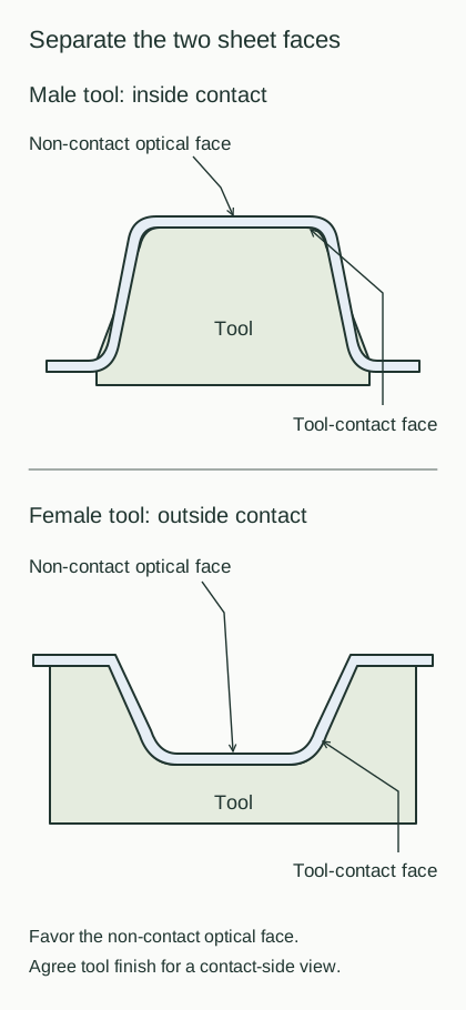
Male and female tooling change which face contacts the tool and which dimensions it controls. Draw the sight line and the region where the user must recognize an object, then overlay the mold surface, mounting edge and trim boundary. Assess an instrument window with the intended background target; a clear sample viewed in isolation can hide distortion that matters in use.
Set protective-film handling from the sheet and process instructions, including when it stays, is removed or is replaced. Keep particles out of contact surfaces during handling and packing. After openings are machined, inspect edges, debris and contact locations. FUNYO's 3-axis and 5-axis CNC operations include holes, slots, trimming and deburring; describe clear-part protection and acceptance alongside the machining drawing.
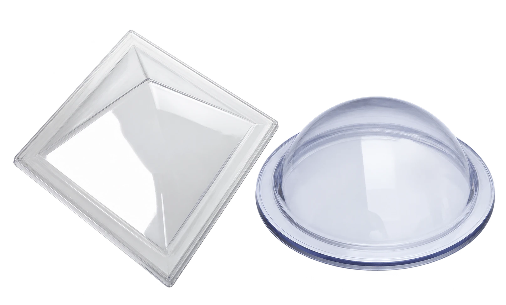
Record scratches, tool marks, local haze, bubbles and viewing distortion as separate acceptance items. The cosmetic-defects and acceptance guide helps organize visible zones, lighting, distance, angle and boundary samples. Keep optical function separate from cosmetic appearance and retain the background target, photographs and mounted condition with sample approval.
Outdoor and flame requirements need grade-specific documentation
Outdoor clear covers need a sheet solution matched to sunlight and installation direction; flame-related applications need the actual grade, thickness and document scope checked. Ordinary clear PC or PETG identifies a material family. State the weathering or flame requirement in the RFQ so the proposed sheet and sample can be evaluated for that use.
Consider temperature, sunlight and restraint in the same assembly. A clear cover may receive sunlight on one side, sit near a heat source on the other and be constrained by a frame. Sampling should represent those relationships. For outdoor equipment, the EV charger enclosure manufacturing guide connects environmental conditions with openings, sealing interfaces and maintenance access.
Record the sheet source, grade, surface orientation and approved sample identity. When a later change affects the sheet or its surface treatment, those records identify which checks need to be repeated. Agree weathering performance and any required test outcome for the project rather than transferring a generic material description into a service-life claim.
PMMA is thermoformable; evaluate FUNYO clear parts with PC and PETG first
PMMA is used for thermoformed components where clear appearance and weathering behavior matter, with impact, edge notches and processing stress considered together. It belongs among the industry's clear-material options. Decide whether it merits a sample by reviewing the actual loads, exposures, temperature and forming geometry, using the same functional brief as for PC and PETG.
FUNYO's confirmed clear-sheet options are PC and PETG; PMMA and other materials are assessed by project. Its own sheet-production facilities cover ABS and PET/PS. List the procurement requirements for a clear grade separately from that in-house sheet scope, including incoming thickness and the finished-wall measurement locations.
Material and geometry influence each other. A deeper shape or tighter transition changes wall distribution and the view through the part. Changing the clear material also calls for reconsidering the tooling and processing setup. Use the heavy-gauge design guide to compare candidate samples against the same geometry, observation target and mounting arrangement.
When should another window or cover structure be considered?
Define the validation method first when the application needs precision imaging, consistent viewing across a curved area or a specialized protective function. Compare a flat window in a separate opaque frame, a smaller optical region, a different sight line or another manufacturing and assembly route. The viewing function may be easier to achieve when it is separated from the structural enclosure.
Dividing optical and structural regions allows visibility, attachment and load support to be addressed separately. An opaque cover can be a useful alternative when the actual purpose is to conceal equipment. If the cover must carry a main structural load, reassess the supports and joints along with the material. A testable use condition makes the comparison more useful than a general question about which plastic is better.
Use one checklist for material, appearance and the mounted sample
Send the material shortlist, environment, viewing requirement and mounted condition together. The final column below is intentionally blank for project information. Use the same fields when quotations and samples arrive so purchasing and engineering compare a common requirement set, including the observations needed for acceptance.
| Item | Points to confirm for PC | Points to confirm for PETG | Project entry |
|---|---|---|---|
| Location and function | Impact protection, viewing or covering duty | Display, viewing or general-cover duty | |
| Temperature and support | Heat source, duration and mounting restraint | Heat source, duration and deformation risk | |
| Impact conditions | Impact event and finished wall | Suitability for the required impact duty | |
| Chemicals and cleaning | Contact substance, duration, temperature and stress | Contact substance, duration, temperature and stress | |
| Grade and sheet documents | Actual sheet and required documentation | Actual sheet and required documentation | |
| Starting and finished thickness | Stock gauge, finished-wall points and support | Stock gauge, finished-wall points and support | |
| Preparation and storage | Predrying, opening and transfer to forming | Grade instructions, storage and opening conditions | |
| Optical face and sight line | Contact face, viewing target and direction | Contact face, viewing target and direction | |
| Appearance acceptance | Scratches, marks, bubbles and boundary samples | Scratches, marks, haze and boundary samples | |
| Outdoor or flame needs | Required performance, orientation and grade documents | Required performance, orientation and grade documents | |
| Machining and protection | Openings, trim, protective film and packing | Openings, trim, protective film and packing | |
| Assembly and sample approval | Frame, fastening state and validation method | Frame, fastening state and validation method |
Download the clear-material selection checklist and attach the finished model, mounting section and main viewing direction. The equipment housing and covers and shrouds families can help describe the component's role. FUNYO responds within 4 hours and provides a suitability assessment and comparison quote within 2 working days, allowing material and appearance requirements to enter the project discussion together.