Thermoformed part dimensions should be compared at an agreed temperature, elapsed time and support condition. Shrinkage reduces a dimension as a hot sheet cools; warpage changes the shape through bending or twisting. A housing can show both. Before changing a tool because a cover will not fit, separate the formed contour, CNC features and assembly restraint, then record where the disagreement actually occurs.
Shrinkage continues as the part cools and leaves the mold
Shrinkage is the reduction in size as the formed sheet moves from its hot processing state toward its service condition. During cooling, the mold constrains the contact surface. Removal releases that constraint while the part may still be cooling. A measurement taken immediately after demolding can therefore differ from a later measurement of the same part, even when both operators follow the drawing.
Identify the surface before assigning the difference to shrinkage. Mold dimensions, tool-contact dimensions and dimensions on the free side describe different boundaries. The free side also reflects local wall thickness and stretching. For an opening, an inside measurement and an outside measurement can differ for geometric reasons. Draw the measuring section and contact points so that the team compares the same feature through each stage.
FUNYO heavy-gauge thermoforming uses starting sheet up to 15 mm (0.59 in), with housings commonly using 8–10 mm (0.31–0.39 in). Starting gauge describes the incoming sheet. Formed wall thickness varies with shape and stretching. Keep the sheet grade, initial gauge, forming direction and thin regions with a distortion record so that a change in material or geometry remains visible during investigation.
Stress relaxation after release can contribute to later movement, while a different ambient temperature can change dimensions through thermal expansion. Record whether the observation is an overall size reduction, a local bend or movement associated with environmental change. A sequence of measurements is useful only when its temperature, timing and support conditions are also known.
Use material shrinkage values as starting points, then correct from the first article
Mold compensation starts with a material allowance and is corrected against the actual first article. The table gives FUNYO heavy-gauge housing design starting points, confirmed and corrected after first-article measurement. Apply them to the selected grade and tooling direction rather than treating a resin name as a complete process specification.
| Material | Mold shrinkage design starting point | Confirmation |
|---|---|---|
| ABS | 0.5–0.7% | Correct after first-article measurement |
| PC | 0.7–1.0% | Correct after first-article measurement |
| PVC | 0.4–0.6% | Correct after first-article measurement |
| PETG | 0.3–0.6% | Correct after first-article measurement |
| PP | 1.5–2.0% | Correct after first-article measurement |
A fabrication guide covering specific polycarbonate-based and other sheet grades gives a mold shrinkage allowance of 0.7–1.0% of the part dimension.1 Check the selected sheet grade against its own documentation. The PC starting range above aligns with that published reference; the final tool compensation follows the first-article results for the actual part.
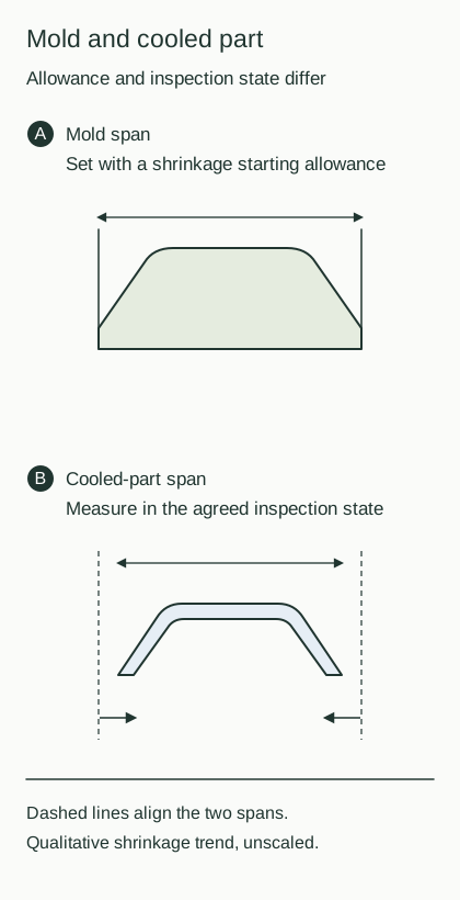
Shrinkage allowance and dimensional tolerance answer different questions. Compensation brings the nominal molded contour toward its target; tolerance defines the permitted variation in the delivered feature. Treat the long edge, opening, mounting surface and machined hole spacing as separate characteristics. This makes it easier to locate a problem than assigning every feature the same material percentage.
A male tool and a female cavity also restrain cooling differently. A shell can grip a male surface, while a cavity controls its outside. Mark the controlled face and release direction on the section. The thermoforming molds guide explains how that choice connects the required surface to the tool construction.
Uneven cooling, wall distribution and restraint create warpage
Warpage develops when regions of a part contract or resist bending differently. A thick transition, a stretched corner and a broad shallow surface can cool and stiffen at different times. Later movement in one area can pull an already stable region away from its intended contour. Investigate the relationship between the areas rather than judging each isolated dimension.
A broad plane has less geometric support than a curved surface. Its perimeter, ribs and attachment positions influence the way it bends. An asymmetric cavity or reinforcement on one side can also create an uneven response. A front photograph may conceal diagonal twist, so include side views and identify the support points used for every image.
Removing a part while it is still soft can allow handling loads to alter its shape. Release direction, local pulling and restraint during removal deserve separate observations. Stacking can then add another load if a long unsupported edge carries weight. Keep forming, trimming, storage and assembly observations separate to identify the stage at which the contour changes.
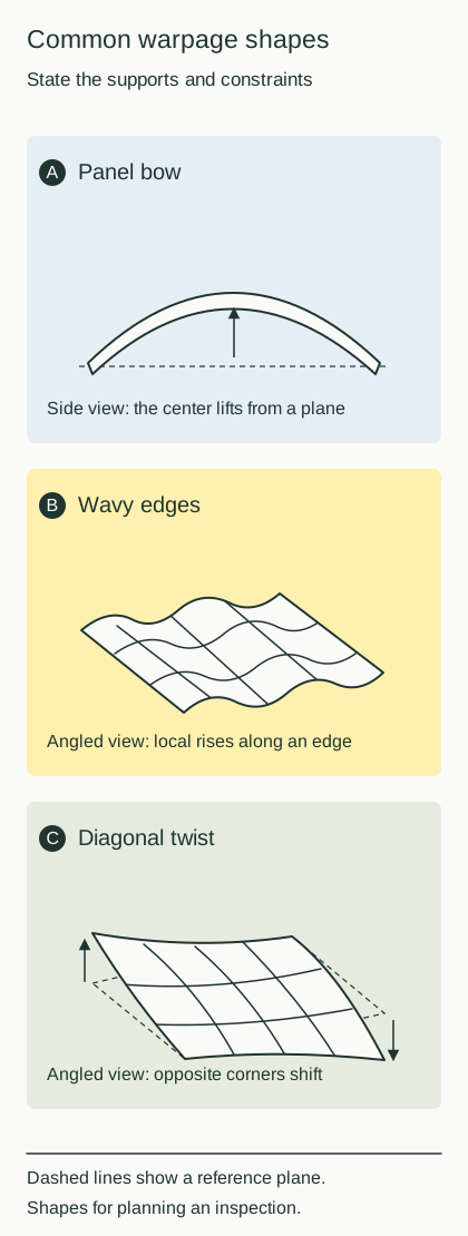
Use repeatable supports to photograph the free shape and mark the direction of movement. Hand pressure can conceal the unloaded contour. Record the free condition first, followed by the installed condition using the actual mounting arrangement. That comparison helps distinguish an appearance concern from an assembly gap or a functional interference.
Ribs, flanges and balanced geometry can support a broad face
Reducing warpage starts with geometry and forming conditions together. Continuous flanges, smooth transitions and purposeful ribs change the stiffness and support path of a face. Check whether the same features introduce deeper drawing or interfere with removal. A section showing the appearance surface, mounts and reinforcement helps connect these choices to the actual assembly.
FUNYO heavy-gauge housing rib design starting points are height no greater than base width, base width at least 3× starting gauge and root radius at least starting gauge, confirmed with the first article. Use these starting points to lay out the geometry, then examine local stretching and measured wall thickness. Locate ribs according to the unsupported span and mounting arrangement.
Balanced geometry reduces obvious asymmetry, but cooling and wall distribution still need observation. Avoid abrupt transitions between flexible and stiff regions. If the appearance requires a broad plane, compare a perimeter flange, an internal frame and a divided cover. Show how each option affects fastener access, visible seams and maintenance before selecting the structure.
FUNYO uses 3-axis and 5-axis CNC for mold making, trimming, holes and slots. A machining fixture must support the part in the agreed condition. Forcing a warped shell flat during machining can leave features in a different relationship after unclamping. Establish formed and machined datums around the intended assembly. Further geometric starting points are in the design guide.
Record temperature, elapsed time and support with the measurement
Comparable dimensions require comparable measurement conditions. A part taken from a warm production area, a part resting in a conditioned room and a part mounted on its frame may have different temperatures and restraints. The inspection plan should identify the environment, the state of the part and measuring equipment, and how those conditions are recorded.
Agree the resting requirement for the material, geometry and intended use. Define when timing begins, how the part is supported and when measurements occur. A note reading only “after cooling” leaves that sequence open to interpretation. The large-part tolerance guide contains the thermal-expansion method and worked scale example, so that the measurement discussion can use a consistent basis.
Free-state inspection describes the part's unloaded shape. Installed inspection describes the shape under the specified mounting constraint. When a frame locates the shell, identify its contact surfaces, attachment positions and tightening sequence. If free-state flatness is also functional, make it a separate characteristic with its own method. Reports should identify which state each result represents.
FUNYO's Nikon VMR-6555 and VMS-5040 vision measuring equipment is suited to trays and other small or medium parts. Agree the measurement method for a large heavy-gauge enclosure around its dimensions, datums and inspection characteristics. Selecting equipment also requires a workable support arrangement, accessible points and a clear link between the reported result and drawing requirement.
Specify shrinkage, flatness and assembly conditions in one checklist
An acceptance requirement combines the feature, method and measurement state. Use the table with the drawing and enter the project details in the blank column. The downloadable shrinkage and warpage checklist matches the webpage. Start with functional assembly conditions, then define the free contour and visible fit.
| Check | Why it matters | How to specify it | Project entry |
|---|---|---|---|
| Sheet grade | Grades within a resin family differ | State material, grade and approved substitutions | |
| Starting gauge | Defines the incoming sheet condition | Separate initial gauge and finished-wall locations | |
| Tool-contact face | Identifies the directly controlled surface | Mark the contact side and critical section dimensions | |
| Shrinkage compensation | Connects tool size to target part size | Record the starting allowance and first-article revision | |
| Measurement temperature | Temperature affects comparison | Agree environment, part and equipment conditions | |
| Resting time | The post-release state can change | Define timing origin, resting conditions and measurement time | |
| Free or installed state | Restraint changes the shape | Identify free inspection or the assembly frame | |
| Support points | Support position changes deflection | Draw support locations and contact directions | |
| Fastening method | Clamping can flatten or twist the shell | State hardware, sequence and agreed installation conditions | |
| Flatness region | A local pad differs from the whole face | Identify the surface, sampling and acceptance method | |
| Critical hole spacing | Relates machining to assembly datums | Mark datums, direction and mating components | |
| Appearance and gaps | Functional fit also has a visible contour | Define observation state, seams and mating profile | |
| Handling and stacking | Storage loads can alter the shape | Agree supports, packaging and stacking conditions | |
| First article and changes | Revisions require a traceable comparison | Link drawing, tool, process and report versions |
For flatness, define the inspected region, reference plane, point collection or scanning method, and the calculation used for acceptance. Flexible shells also need a gravity direction and clamping condition. A drawing note asking only for a flat surface gives purchasing and inspection teams too little information to reproduce the same decision.
Keep contour results, critical dimensions, local thickness and actual trial assembly under the same first-article version. Following a mold or fixture change, repeat the agreed method to see what moved. Use the cosmetic acceptance guide for visible conditions and the sampling and first-article guide for the approval sequence.
Compare frame restraint or another process for demanding free-state flatness
Demanding free-state flatness across a broad unsupported face calls for a comparison of frame support, divided construction and alternative processes. Establish whether the requirement serves a seal, moving clearance, appearance or a mounting interface. The function determines whether the shell must hold that shape alone or whether the equipment structure can supply restraint.
Where a stable frame supports the cover, specify the free contour separately from the installed functional surface. Where an unloaded plane itself performs the function, compare sheet metal, machined plate or another route using the same measurement method. Include forming geometry, secondary machining, support components and validation in that comparison so the chosen route addresses the complete requirement.
Next, submit the drawing, sheet choice, distortion photographs, support sketch and measurement record together. FUNYO responds within 4 hours and provides a suitability assessment and comparison quote within 2 working days. The quality assurance page describes the inspection equipment; use the actual dimensions and mounting needs to agree how the first article will be measured, fitted and approved.