Compare thermoforming quotes by separating the initial investment, the recurring part cost and the delivery scope. A lower tooling figure answers a different question from a lower unit price or freight included to your plant. For equipment covers, the purchased sheet area, secondary machining, cosmetic acceptance and packaging can materially change the delivered result. Issue the same drawing revision, quantity schedule and acceptance requirements to each supplier before comparing the totals.
Separate tooling, fixtures and first articles from production pricing
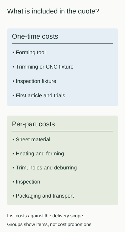
One-time charges establish the manufacturing and acceptance method. Ask for forming tooling, trimming or CNC fixtures, inspection gauges and first articles as separate items. The forming tool controls the main shape. A machining fixture supports the shell and establishes its cutting position. A checking fixture may locate the part for repeatable measurement or an assembly check. Similar descriptions can cover quite different deliverables, so record what each item actually does.
For the same part scope, 方宇(FUNYO) heavy-gauge thermoforming tooling costs less than 1/10 of a comparable injection mold. That comparison applies to tooling fees only. Use it when considering the initial investment between those forming routes, then add the quoted recurring operations and planned quantities to compare the project. Keep tool changes, storage and later use visible rather than allocating every initial charge into an unexplained part price.
Housing projects with annual demand of about 3,000 pieces and an annual supply agreement can apply for a tooling-fee waiver evaluation. Provide the demand forecast and the expected release schedule together. The evaluation outcome and treatment of the charge belong in the quotation and agreement, alongside ownership, changes and the arrangements if the project ends. The purchasing commitment should reflect the demand the business can support.
First-article charges also need a defined output. Identify whether the offer covers a formed shell, a fully machined sample, dimensional results or an assembly trial. Ask which tools or checks would change after a drawing revision and how the next sample would be released. The sampling and first-article guide helps distinguish sample condition, supporting records and production approval.
Unit cost starts with purchased sheet, including the material removed
A delivered part includes sheet, heating and forming, trimming, holes, deburring, inspection, packaging and transport. The sheet allowance includes material held by the clamp and material removed after forming. Machining allowances depend on the retained outline, openings and edge condition. Inspection and protection depend on what the buyer will accept at delivery. Covers with similar overall dimensions can therefore have different cost structures.
Define material utilization using a consistent area basis. Developed surface area, projected footprint and purchased sheet area describe different things for a curved part. The calculation below uses a hypothetical flat nesting layout to show the effect of clamping and offcuts. Actual forming also requires a check of draw, wall distribution and available sheet sizes. Keep those engineering decisions attached to the purchasing comparison.
Example, not a quotation: assume one flat component uses 0.60 m² of useful area from 1.00 m² of purchased sheet. Area utilization is 0.60 ÷ 1.00 × 100% = 60%. The combined clamp and trim allowance is 0.40 m², or 40%. These assumed areas contain no material price and describe no measured FUNYO consumption or yield.
| Area item | Example value | Calculated result |
|---|---|---|
| Purchased sheet area | 1.00 m² | Calculation denominator |
| Useful component area | 0.60 m² | Utilization 60% |
| Clamp and trim allowance | 0.40 m² | Offcut share 40% |
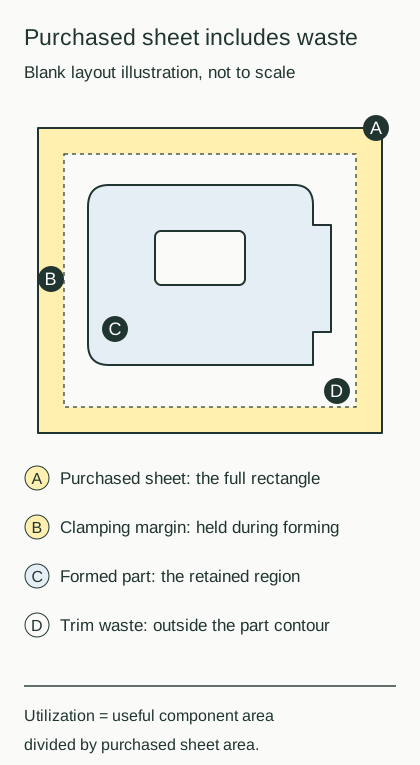
The diagram shows clamp and trim allowances; the area calculation above is an example, not a quotation.
Sheet utilization and secondary operations can outweigh the difference seen by looking at forming alone. A different sheet format or nesting arrangement can change the material input, fixture, toolpath and package. Compare the revised delivered scope as a whole. Record any scrap recovery or credit according to the supplier's offer rather than assuming a recovery value before the commercial terms are known.
FUNYO uses 3-axis and 5-axis CNC for tools, trimming and deburring, holes and slots. Distinguish the formed envelope from the features cut afterward, and identify datum surfaces and retained edges. A group of openings approached in one setup creates a different machining plan from openings spread across several faces. Support, tool access and refixturing help explain the quoted machining work.
Deep draws, secondary features and acceptance conditions add work
Deep draws, extensive machining, demanding appearance criteria, tight tolerances and small runs of multiple versions commonly increase the required work. Drawing redistributes sheet material, so a thin deep corner can lead to changes in starting gauge, radii, depth or the part split. State the functional finished wall and mounting needs, then compare the options in the heavy-gauge design guide.
Price machining by the operation and access it requires, as well as the feature count. A pattern that shares an approach direction and clear datum differs from a pattern needing several setups. Keep the real ventilation, wiring and installation requirements on the RFQ drawing. Identify optional styling cuts separately so engineering can decide whether their appearance justifies the extra machining and inspection.
Cosmetic requirements affect protection, sorting and acceptance. Define the visible face, viewing conditions, acceptable contact marks and boundary samples. Include color, texture and the expected consistency between batches. The cosmetic defects and acceptance guide provides a way to describe these conditions so each supplier prices the same finished appearance rather than interpreting a general request for a good finish.
Tighter tolerances can affect forming, support, machining and measurement. Identify the mating datums and functional dimensions before tightening the entire drawing. The large-part tolerance guide explains how to separate interface requirements from the rest of the envelope. With several versions, also record batch splitting, changeovers and revision identification. The annual aggregate quantity can hide much smaller production releases with different manufacturing effort.
Compare quotations against one delivery-scope table
Fair comparison starts with the same revision, release quantity and delivery condition. Use the table to capture what each supplier includes; the supplier columns are intentionally blank for their replies. For requested surface effects or assembly, identify the operation, responsible party and acceptance scope in the RFQ and quotation. Keep the original offers so a later revision can be checked against the actual commercial basis.
| Cost item | Included scope | Supplier A | Supplier B | Supplier C | Notes |
|---|---|---|---|---|---|
| Forming tool | Tool manufacture and change scope | Separate initial charge | |||
| Fixtures | Trimming and CNC support and location | Record applicable revision | |||
| Inspection gauges | Measurement or mating-check tools | Record purpose and ownership | |||
| First article | Sampling, checks and release records | Define sample condition | |||
| Sheet | Material, gauge, color and allowance | Include clamp and offcuts | |||
| Forming | Heating, forming and part removal | Use the same geometry | |||
| Trimming | Final outline and edge condition | State trimming method | |||
| Openings | Holes, slots and other cutouts | Match drawing features | |||
| Deburring | Treatment of machined edges | Agree accepted condition | |||
| Surface | Requested appearance and treatment scope | Identify operation provider | |||
| Inspection records | Dimensions and delivery records | Match agreed inspection scope | |||
| Packaging | Protection, separation and packing | Match transport and unpacking | |||
| Transport | Delivery terms and named destination | Align costs and responsibilities | |||
| Tool ownership | Ownership, storage and transfer | Compare contract terms | |||
| Payment and validity | Payment milestones and offer expiry | Record applicable conditions |
Download the quote comparison CSV and enter each supplier's actual response. The web table and download use the same comparison items, with room for the purchasing team to complete the supplier columns.
For transport, compare the named place as well as the allocation of cost and responsibility. See the thermoforming RFQ checklist for Incoterms and the information to issue with the enquiry. Package size, separators and handling can change the shipping arrangement. Include unpacking and the receiving inspection where cosmetic parts need protection through delivery.
Quantity breaks also need a definition. Ask whether a price applies to a purchase order, a manufacturing batch or an annual commitment. Calculate expenditure using the intended release pattern and keep tooling, changes, repeat orders and freight separate. The break-even worksheet shows how initial and recurring charges combine. Confirm that every offer uses the same batch basis before treating the difference as a unit-price saving.
A useful clarification round asks each supplier to mark the same drawing and return an itemized scope before the price is revised. Record which openings are machined, which edges are supplied as cut and which records accompany the shipment. Where an operation is bundled, ask what happens to the offer if that operation changes. Keep an agreed difference in scope visible instead of forcing unlike proposals into a single unit-price column. Once the scope is aligned, retain the resulting revision with the purchase order so receiving inspection can use the same appearance, packaging and dimensional requirements that purchasing compared.
Reduce cost by changing material use and the necessary operations
Practical cost reduction starts with nesting, optional machining, nonfunctional tolerances and opportunities to share gauge or color. Combining components deserves a check of draw depth, installation and service access at the same time. A continuous shell may reduce joints while changing material input or machining. Bring the revised drawing back to the comparison table so the apparent saving includes the complete supplied part.
A supply agreement can support discussion of release timing, revisions and stock preparation. First distinguish stable features from areas likely to change. Consider which tools and setups can serve the versions together, and obtain design approval before standardizing appearance or dimensions. A purchasing suggestion becomes useful when the engineering owner confirms the revised requirements and suppliers can quote them on the same basis.
FUNYO carries out heavy-gauge thermoforming, thin-gauge thermoforming and CNC in-house, from design and tooling to production shipment. Heavy gauge suits medium-to-large parts with annual demand from hundreds to a few thousand pieces. Thin-gauge trays have a separate quantity basis: trial runs start at 50 pieces and production at 500 pieces. Itemize a shell and its thin-gauge insert separately so the quantity conditions follow the appropriate process.
Compare injection molding when volume is high and the design is stable
At high volume with a stable design suited to injection molding, compare the full project again. The balance between initial tooling and recurring processing changes with geometry, material and secondary work. Use matching delivered scope and actual supplier offers, then read the heavy-gauge versus injection molding guide alongside the break-even worksheet. The relevant crossover belongs to the project being quoted.
Send the drawing, material requirements, release plan and completed scope questions together. FUNYO accepts STEP, IGES, DWG, PDF or photos; photos with dimensions can start the discussion where drawings are unavailable. Response is within 4 hours, with a suitability assessment and comparison quote within 2 working days. Heavy-gauge tooling takes about 1–3 weeks; schedule sample approval, production and transport as separate stages after the tooling plan.