Choose between thermoformed and sheet metal enclosures by separating the appearance cover from the structure. Heavy-gauge thermoforming suits large curved covers with rounded transitions. Sheet metal deserves an early comparison for load-bearing boxes, grounding paths and shielding structures. A metal frame with a thermoformed outer cover can also be quoted as its own design route. Allocate the functions first, then compare initial investment, recurring work and future changes against the same delivered scope.
Sheet metal is cut and bent; thermoforming shapes heated sheet over a tool
The manufacturing mechanism changes how an enclosure should be divided into components. Sheet metal uses cutting, punching, bending and joining to create panels, boxes and brackets. Thermoforming softens plastic sheet and shapes it against a tool, followed by trimming and machining of openings. Moving the existing geometry directly from one process to the other can preserve details that would work better elsewhere in the assembly.
A curved shell can provide the appearance surface while separate hardware or a frame provides small connection features and loaded interfaces. Show the boundary between cover and chassis, split lines, access openings and fastener directions on the concept drawing. Decide what locates the assembly and what carries the equipment load. Those decisions are more useful than replacing the metal thickness in the existing model with a plastic thickness.
方宇(FUNYO) carries out heavy-gauge thermoforming, thin-gauge thermoforming and CNC in-house, from design and tooling to production shipment. Maximum heavy-gauge part size is 2600 × 1600 × 600 mm (102.4 × 63.0 × 23.6 in). Arrange the metal frame design and supply separately within the project, and provide its drawing or mounting interface when requesting the formed cover. This establishes the boundary of the component being quoted.
Compare appearance, structure and delivery scope in separate rows
Use the same functional requirements and supplied condition for both routes. The sheet metal and hybrid columns below are qualitative. FUNYO's heavy-gauge starting-sheet range is 6–15 mm (0.24–0.59 in), with housings commonly using 8–10 mm (0.31–0.39 in). Local finished wall changes with stretching and should be considered with the support and mounting arrangement. The project column is blank for the equipment requirements.
| Comparison item | Heavy-gauge thermoforming | Sheet metal | Hybrid design | Your project |
|---|---|---|---|---|
| Shape freedom | Large curves, radii and continuous covers | Direct route for flats and bends; complex curves need further forming or joining | Frame carries structure; curved cover defines the envelope | |
| Appearance and color | Specify sheet color, texture and formed surfaces | Specify metal surface and required finishing | Define cover and frame appearance separately | |
| Load support | Design around finished wall and support | Design the load path through metal structure | Put primary loads into the metal frame | |
| Grounding and shielding | Design conductive structures and validation by project | Check continuity, seams and grounding | Frame or separate metal layer provides the function | |
| Weight | Estimate from density, finished wall and area | Estimate from metal density, gauge and brackets | Add frame, cover and connection hardware | |
| Tooling or fixtures | Itemize heavy-gauge tools and compare with injection tooling for the same scope | Itemize cutting, bending and welding fixtures by route | Separate cover tooling from frame fixtures | |
| Design changes | Separate shape changes from CNC opening changes | Separate flat pattern, bends, joining and finish changes | Retain frame interfaces where practical and price cover changes separately | |
| Lead time | Heavy-gauge tooling about 1–3 weeks; add sampling and production | Schedule material, shaping, joining and finishing | Coordinate both sample routes and combined fit checks | |
| Suitable quantities | Medium-to-large parts, hundreds to a few thousand annually | Compare geometry, batches and manufacturing route | Calculate frame and cover revisions separately |
Download the enclosure process comparison CSV and enter your equipment requirements in the final column. The web and download use the same comparison items.
After screening the routes, identify every supplied component. Comparing a metal cabinet, a frame-and-cover assembly and a bare plastic shell mixes different structural and commercial scopes. Issue an assembly list and ask each supplier to identify its own deliverables. Include separately purchased frames, connection hardware and required operations in the project total before selecting the route.
Design large curves and rounded transitions around the formed cover
Heavy-gauge thermoforming offers a route to continuous curved covers and rounded transitions. Designing the shape and split lines together can place seams away from the principal viewing direction while preserving access for service. Consider draft, radii, draw depth and the mounting regions during that work. An appearance model is more useful when it already acknowledges the surfaces needed for release and attachment.
Sheet metal is direct for flat panels and bends. Complex continuous curves can introduce other forming methods, joined pieces and blending operations. Give both routes the same target contour, edges and appearance requirements, then ask which operations are necessary. Reducing a seam can change tool size, part handling and shipping as well as appearance, so compare the revised component as a complete proposal.
Sheet selection also affects the finished appearance. FUNYO evaluates ABS, PC, PVC, PETG and PP for heavy-gauge parts. Define color, texture, visible faces and cleaning exposure with the material. Include the machined openings, cut edges and gaps in the mounted assembly when discussing appearance. Identify the regions where tool contact is acceptable and the regions seen by the operator.
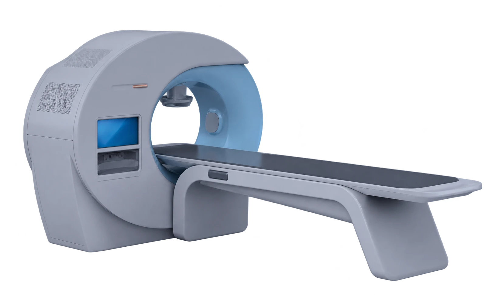
The large medical equipment housing photograph illustrates enclosure form. Define the material, load and mounting requirements for the equipment in your own project. Mark the functional interfaces separately from the visible faces so purchasing and engineering discuss the same component. The equipment housings and covers and shrouds pages describe the related product ranges.
Allocate load paths, grounding and shielding to the appropriate structure
Load support, grounding and electromagnetic shielding require an explicit design and validation route. A metal frame can carry the primary equipment loads while the plastic cover provides the outer envelope. Draw the load path between equipment, brackets and base before assigning additional tasks to the shell. Give fasteners stable support and a clamping surface so the connection avoids concentrating load in a stretched corner.
Electrical conductivity is a starting material characteristic; assembled continuity depends on joints, seams, openings and the grounding connection. If a plastic-covered region needs shielding, the project can consider a separate metal inner structure or conductive layer with the responsible provider. Define that provider's scope and validation. Quote FUNYO's cover forming and machining against their own drawing requirements, and validate the electrical function at the equipment level.
Weight depends on material and structure, so there is no universal reduction percentage. Estimate each region using material density, finished wall and surface area, then add the frame, flanges, brackets and hardware. For a drawn cover, divide the shell into regions with representative finished walls. That is a more useful preliminary calculation than multiplying the complete surface by the starting sheet gauge.
Insulating covers also need a service-environment definition. Heat, cleaning exposure, impact and assembly stress can change the material choice. Where electrical or protective functions are involved, identify the equipment requirement and test condition before choosing the sheet. Allocate appearance, structure, electrical functions and maintenance explicitly, then decide which regions need metal and which can use a plastic cover.
A metal frame and plastic cover should share mounting datums and service access
In a hybrid design, the metal frame provides structural support and interfaces while the thermoformed cover provides curves and enclosure. Freeze the common mounting datums before finalizing split lines, openings and removal direction. Machined holes can correspond to the frame interfaces, while appearance edges and assembly clearances receive their own functional allowances. This keeps the locating tasks understandable across the assembly.
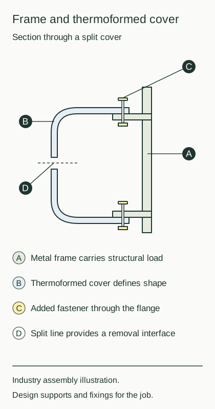
Common industry connections include frame-mounted nuts, rivet nuts, separate brackets, latches and hinges. The shell provides a clearance opening or mounting face; the frame supplies threads and primary support. Spread clamping force through an appropriate contact area. The fastening and assembly guide explains these interfaces. Validate tool access, removal and tightening using the actual combined parts.
Allocate tolerances around assembly datums. List dimensions that control hole locations, split-line gaps and equipment interfaces separately, and specify whether inspection uses the free part, a support fixture or the assembled condition. The large-part tolerance guide helps organize those requirements. Frame and cover suppliers should use the same interface drawing and revision history so combined fit checks can identify the source of a mismatch.
Machining also needs appropriate support. FUNYO uses 3-axis and 5-axis CNC for tools and for trimming, deburring, holes and slots in formed parts. Include the machining datum, retained outline and mounting openings in the RFQ, together with the frame model or interface dimensions. Check draw, radii and part splits using the heavy-gauge design guide while these interfaces are still being defined.
Separate initial investment, recurring cost and the cost of a design change
Compare sheet metal and thermoforming through actual route-specific quotations. Itemize initial tools or fixtures, recurring operations and future changes. For a formed cover, include tooling, fixtures, forming, CNC, inspection and packaging. For metal, identify the required cutting, bending, joining and finishing. A hybrid total combines the frame, cover and assembly-related items at the same quantity, destination and acceptance scope.
FUNYO heavy-gauge thermoforming tooling costs less than 1/10 of a comparable injection mold for the same part scope; the ratio concerns tooling fees only. Compare sheet metal using its actual quoted fixtures and operations. The break-even guide explains how initial and variable costs combine. Populate that method with the current project's relevant costs and quantities rather than carrying a ratio between unrelated manufacturing routes.
Classify a revision before requesting a change price. A new opening can affect CNC programming and support, a new primary curve can affect the forming tool, and a changed frame interface can affect both suppliers and their fit checks. Preserving stable frame interfaces while separating appearance areas likely to change makes the scope of each revision easier to price and approve.
Schedule tooling, samples, approval and production as distinct stages. Heavy-gauge tooling takes about 1–3 weeks; the project also needs changes, combined fit checks and transport. Where suppliers work in parallel, align interface freeze and sample availability between the frame and cover. Record the treatment of existing tools and inventory when comparing a revised design with the current version.
Prefer a metal-route comparison for flat structural boxes and high heat
Flat bent boxes with significant loads, conductive shielding requirements or high-temperature conditions deserve an early metal-route comparison. Very small quantities with straightforward appearance requirements also warrant a review of actual sheet metal operations. Start with function, material and manufacturable geometry, then compare expenditure. Established equipment safety and performance requirements remain inputs to the process decision.
For charging equipment, the EV charger enclosure guide compares thermoforming, injection molding and sheet metal within that application; this article covers the general equipment decision. Send FUNYO the envelope and interface drawings, material conditions, quantity plan and mating frame information. Response is within 4 hours, with a suitability assessment and comparison quote within 2 working days. Arrange metal mating components separately within the project.