Thermoforming shapes heated plastic sheet against a single-sided tool, allows it to cool, and trims the formed blank into a usable part. For a first sourcing decision, identify the part's contact face, starting sheet gauge and finished openings. Those choices explain much more than a product photograph about whether a sheet-forming route fits the design.
Heating, forming, cooling and trimming create the finished part
The forming process starts with sheet that can stretch when heated. Holding the sheet around its edges lets the forming equipment bring the softened material to the tool. In vacuum forming, removing air between the sheet and mold creates the pressure difference that brings the material against the surface. The sheet follows a path rather than receiving an identical amount of stretch everywhere.
Cooling helps retain the shape, while the material also changes dimension as its temperature falls. The part then leaves the tool with material around the finished outline. Trimming removes that allowance, and subsequent operations create the openings and edges needed for assembly. A quotation should identify the delivered condition so engineering and purchasing are comparing the same item.
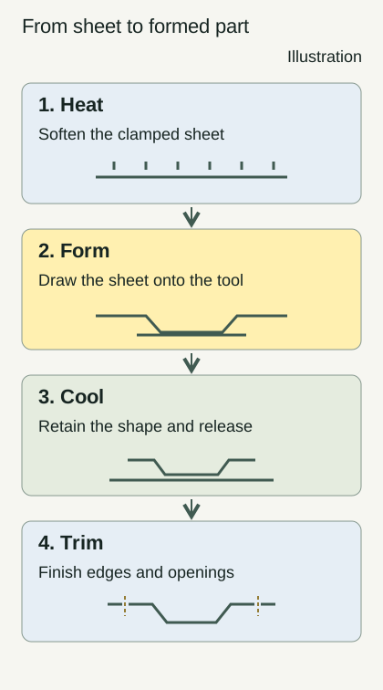
The mold, fixture and cutting path can control different features. A broad curved face may originate in forming, while an installation hole receives its location during finishing. Treating those features separately makes the drawing easier to discuss. Send an assembly section with the first RFQ so the supplier can see how the outline, attachments and adjacent parts work together.
Vacuum forming, pressure forming and twin-sheet forming describe different methods
Vacuum forming uses a pressure difference to draw softened sheet onto a tool. Vacuum/pressure forming adds air pressure from the opposite side to help the material follow the mold. Twin-sheet forming brings separately formed hot sheets together at their contact areas to make a hollow structure. The names identify ways of shaping and combining sheet; the part requirements still determine the tooling and delivery scope.
Ask a supplier which combination of equipment, tool access and material suits the actual drawing. A single visible contour, a hollow section and a closely spaced detail create different questions about how the material moves and how the part is removed. Listing the required geometry and accessible faces helps the supplier explain the proposed route, including any finishing after the forming stage.
方宇(FUNYO) was founded in 2004 in Doumen, Zhuhai, Guangdong. Its thin-gauge operation added high-speed vacuum/pressure formers in 2022. That equipment information belongs to thin-gauge tray production. Present a heavy-gauge housing, a thin-gauge insert and a twin-sheet structure as separate supply requests, with their own drawings and acceptance conditions, rather than selecting a process solely from its name.
Starting gauge and part function separate thin-gauge and heavy-gauge work
Starting gauge describes the sheet entering the process. Thinner sheet commonly becomes packaging trays and locating inserts, while thicker sheet is used for covers, housings and large handling trays. Feeding, clamping, heating and finishing arrangements also depend on the production route. The wall in a formed corner depends on the stretch experienced by that region as well as the sheet selected at the beginning.
FUNYO's heavy-gauge working range is 6–15 mm (0.24–0.59 in), with housings commonly starting at 8–10 mm (0.31–0.39 in), and sheet up to 15 mm (0.59 in). Record the purchased gauge separately from the local wall thickness that matters to the assembly. Mark areas to measure on a sample, especially around deep regions, corners and mounting interfaces, and define the support condition used during inspection.
FUNYO has produced thin-gauge trays since 2013. Its heavy-gauge work began in 2023, followed by a dedicated division with heavy-gauge forming and five-axis equipment in 2025. Use Thin-Gauge vs Heavy-Gauge Thermoforming for Parts to organize the route, material and acceptance questions for each type of part. The distinction is most useful when it leads to a clear specification.
Male molds, female molds and the contact face guide the drawing
A male mold is covered by the sheet on its outside surface, while a female mold receives sheet into a cavity. Identify the face that touches the tool before deciding which contour controls assembly. The opposite face also reflects the local sheet thickness and stretch distribution. Show the appearance face, mating interface and inspection face separately when they serve different functions.
Draft and radii provide space for release and material distribution. Changes in depth, nearby raised features and narrow transitions affect the forming path. If the material has difficulty reaching a region, the team can compare a broader transition, another forming direction or a split part. For an interface requiring controlled location, connect the formed surface to the datum used in later machining and inspection.
Read Heavy-Gauge Thermoforming Design: Draft and Walls when preparing those sections. Large-Part Thermoforming Tolerances: Drawing Guide explains how a freely resting part and a supported part can produce different inspection results. Specify which condition represents the intended assembly, and use that condition consistently when evaluating the sample and subsequent production.
Finishing turns a formed blank into an assembly-ready part
Trimming, openings and deburring belong in the delivery scope. A heavy-gauge part can be supported in a fixture while a cutting tool follows the finished contour. A thin-gauge tray can be separated by a cutting die and press. Both routes require the finished edge, retained surfaces and relationship to neighboring parts to be identified before the manufacturing plan is agreed.
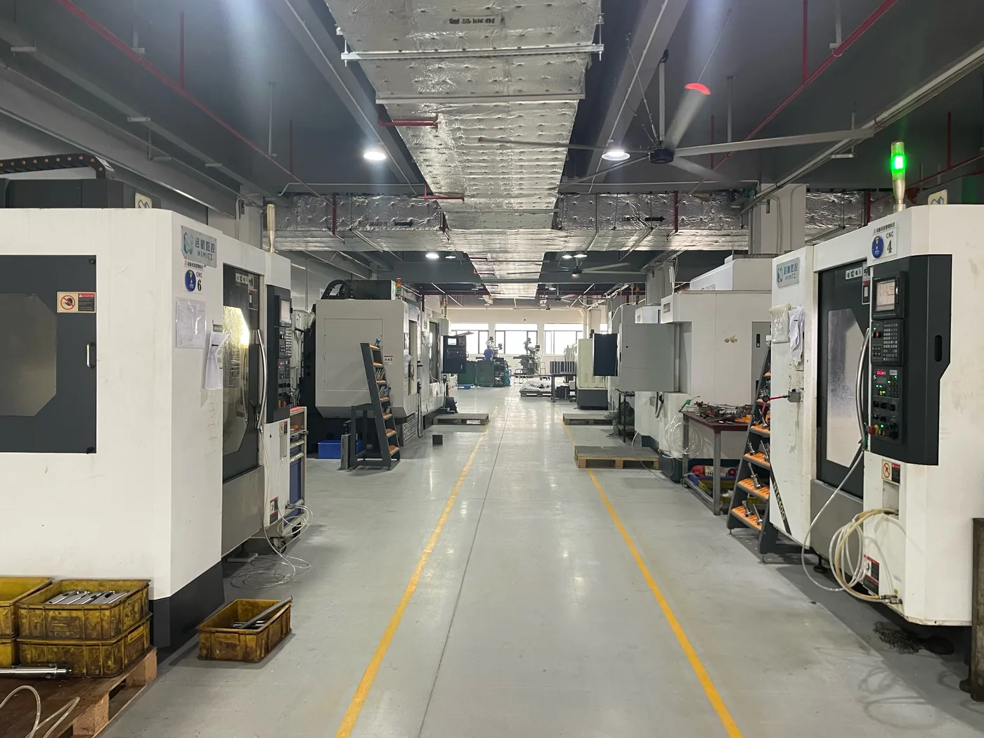
FUNYO uses three-axis and five-axis CNC for tooling, trimming and deburring formed parts, holes and slots, and machined components made to drawings. Its thin-gauge workshop has a die-cutting press. Mark display apertures, mounting holes, cable passages and outside edges with their intended function and inspection approach so the supplier can assess both tool access and support during finishing.
Color, texture and service conditions should travel with the material request. Thermoforming Materials Guide: ABS, PC, PVC & PP provides a starting structure for the selection discussion. Follow that discussion with the intended grade and sample requirements. A combined forming, finishing, inspection and packing scope makes it easier to explain why quotations differ even when their headline part description looks similar.
When should injection molding or sheet metal be compared first?
Start process selection with the functions and delivered assembly, then examine how quantity changes project cost. Concentrated internal attachment features, a mature repeat-production design or a requirement for metal to provide grounding and structural support can justify an injection-molding or sheet-metal proposal. Compare the visible contour, attachment components and finishing within the same scope, rather than comparing a formed skin with an assembled alternative.
A single-sided forming tool controls one face and can simplify tooling construction compared with an injection mold with a cavity and core. That affects the initial tooling and revision work, while finishing and assembly still contribute to the delivered cost. Drawing revisions, material and quantity can change the balance between initial expense and recurring part cost. Ask each supplier to identify which scope and assumptions its quotation covers before calculating the difference. FUNYO heavy-gauge tooling takes about 1–3 weeks, compared with about 6–10 weeks for comparable injection tooling; heavy-gauge tooling costs less than 1/10 of comparable injection tooling for the same part scope. This ratio compares tooling fees only.
Use Thermoforming vs Injection Molding: Break-Even Cost for that calculation and Heavy-Gauge Thermoforming vs Injection Molding for the process comparison. For an equipment cover, EV Charger Cover: Thermoforming, Injection or Metal separates the appearance skin from structural and complete-equipment requirements. Carry those distinctions into a common RFQ so every route is evaluated against the same intended function.
Use a trilingual glossary to align drawings and purchasing language
The glossary connects Chinese, English and Japanese names to the same physical feature or operation. Each definition gives the object being discussed; the related article develops the drawing, inspection or sourcing question. The downloadable English CSV keeps the trilingual terms, English definitions, Chinese synonyms and full article URLs. Use the terms alongside the drawing when discussing the same feature with suppliers.
| 中文 | English | 日本語 | Definition | Related article |
|---|---|---|---|---|
| 吸塑 | Thermoforming | 熱成形 | A process that shapes heated plastic sheet on a tool, then cools and trims it. | Thin-Gauge vs Heavy-Gauge Thermoforming for Parts |
| 真空成型 | Vacuum forming | 真空成形 | A forming method that removes air between the sheet and tool to bring them together. | — |
| 正负压成型 | Vacuum/pressure forming | 真空・圧空成形 | A method using vacuum and air pressure on the opposite side of the sheet to aid forming. | — |
| 双片成型 | Twin-sheet forming | ツインシート成形 | A method joining separately formed hot sheets at their contact areas to create a hollow part. | — |
| 厚片吸塑 | Heavy-gauge thermoforming | 厚板真空成形 | The forming of thicker starting sheet into housings, covers or large trays. | Thin-Gauge vs Heavy-Gauge Thermoforming for Parts |
| 薄片吸塑 | Thin-gauge thermoforming | 薄板真空成形 | The forming of thinner sheet into packaging trays, locating inserts and similar parts. | Thin-Gauge vs Heavy-Gauge Thermoforming for Parts |
| 片材 | Sheet stock | シート材 | Plastic stock with a specified material and surface before heating and forming. | Thermoforming Materials Guide: ABS, PC, PVC & PP |
| 起始板厚 | Starting gauge | 初期板厚 | The thickness of the sheet before heating and stretching, distinct from local formed wall thickness. | Heavy-Gauge Thermoforming Design: Draft and Walls |
| 阳模 | Male mold | 雄型 | A tool whose outside surface is covered by the sheet, primarily defining the part inside. | Heavy-Gauge Thermoforming Design: Draft and Walls |
| 阴模 | Female mold | 雌型 | A cavity tool into which the sheet is drawn, primarily defining the part outside. | Heavy-Gauge Thermoforming Design: Draft and Walls |
| 贴模面 | Tool-contact surface | 型接触面 | The face directly contacting the mold and following the shape of its surface. | Heavy-Gauge Thermoforming Design: Draft and Walls |
| 拔模角 | Draft angle | 抜き勾配 | A sidewall angle along the release direction that helps the formed part leave the tool. | Heavy-Gauge Thermoforming Design: Draft and Walls |
| 圆角 | Radius | コーナーR | A curved transition between adjoining surfaces, specified on the inside or outside of a corner. | Heavy-Gauge Thermoforming Design: Draft and Walls |
| 面积拉伸比 | Areal draw ratio | 面積延伸比 | The formed surface area divided by the original sheet area participating in that stretch. | Heavy-Gauge Thermoforming Design: Draft and Walls |
| 深度比 | Depth ratio | 深さ比 | The forming depth compared with a defined opening dimension in a stated direction. | Heavy-Gauge Thermoforming Design: Draft and Walls |
| 辅助柱塞 | Plug assist | プラグアシスト | A mechanical pre-stretching method that helps distribute sheet before it reaches the mold. | Heavy-Gauge Thermoforming Design: Draft and Walls |
| 夹持边 | Clamping margin | クランプ余白 | Material around the part used for holding and locating it during forming or finishing. | Heavy-Gauge Thermoforming Design: Draft and Walls |
| 修边 | Trimming | トリミング | Removal of excess formed material to bring the part edge to its finished outline. | Heavy-Gauge Thermoforming Design: Draft and Walls |
| 冲切 | Die cutting | 抜き加工 | Cutting a formed part to a specified outline using a cutting die and press. | — |
| CNC修边 | CNC trimming | CNCトリム | Removal of edge stock or creation of openings by a numerically controlled cutting tool. | Thermoforming RFQ Checklist: Scope and Drawings |
| 网纹 | Webbing | ウェビング | Excess sheet folding between nearby raised features or deep forming areas. | Thermoforming Defects: Webbing, Chill Marks & Checks |
| 冷斑 | Chill marks | チルマーク | A local surface mark associated with sheet contacting a cooler area early in forming. | Thermoforming Defects: Webbing, Chill Marks & Checks |
| 白化 | Stress whitening | 白化 | A pale appearance developing where plastic experiences local stretching or stress. | Thermoforming Defects: Webbing, Chill Marks & Checks |
| 收缩率 | Shrinkage rate | 収縮率 | A ratio describing dimensional reduction as material cools and changes condition after forming. | Heavy-Gauge Thermoforming Design: Draft and Walls |
| 首件 | First article | 初品 | An initial sample made to the agreed process for checking drawing and acceptance requirements. | Thermoforming Samples and First Article Approval |
| 测量基准 | Measurement datum | 測定基準 | A reference establishing the position, direction and origin for a measurement. | Large-Part Thermoforming Tolerances: Drawing Guide |
| 定位治具 | Locating fixture | 位置決め治具 | A device holding and supporting the part in a defined position during machining or measurement. | Thermoforming RFQ Checklist: Scope and Drawings |
| 防叠结构 | Anti-nesting feature | 貼り付き防止形状 | A feature limiting tray nesting depth and leaving space for separation and air entry. | Thermoformed Automation Trays: Tolerances and ESD |
| 表面洁净度 | Surface cleanliness | 表面清浄度 | A requirement describing residue on a part contact surface using an agreed inspection method. | Cleanroom Thermoformed Trays: Cleanliness Specs |
| 询价资料 | RFQ package | 見積依頼資料 | The information defining drawings, quantities, material and delivery scope for a quotation. | Thermoforming RFQ Checklist: Scope and Drawings |
Download the trilingual thermoforming glossary and add your internal preferred terms beside the project drawing. For tray separation, read Thermoformed Automation Trays: Tolerances and ESD. For environmental and contact-surface requirements, use Cleanroom Thermoformed Trays: Cleanliness Specs. These questions belong in separate specification lines, even when the same tray has to satisfy both.
Send the use conditions, drawing and delivery scope as the next step
The next step is a shared information package that lets a supplier assess the proposed forming route. Explain how the part attaches, what it touches and how it moves through handling. Provide the outside shape, important sections, starting gauge and quantity plan. Identify the mounting features, measurement supports, appearance reference and packaging condition so the technical discussion can work from an actual supply requirement.
FUNYO's maximum heavy-gauge part size is 2600 × 1600 × 600 mm (102.4 × 63.0 × 23.6 in). FUNYO responds within 4 hours and provides a suitability assessment and comparison quote within 2 working days. Prepare the inputs with Thermoforming RFQ Checklist: Scope and Drawings, then use Thermoforming Guides to continue with the relevant design, materials or inspection topic.